4.Assembling the Solar Tracking Kit
Things to note before assembly:
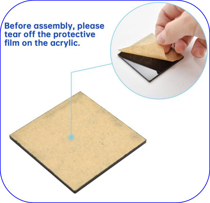
1.Before assembly, please tear off the protective film on the acrylic boards.
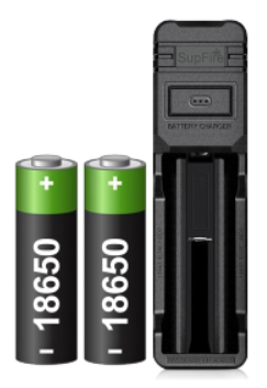
2.You will need to prepare yourself a 18650 battery as well as a battery charger.
The following parameters are available for your purchase:
Specifications |
|
|---|---|
Size |
18650 |
Positive Terminal: |
|
Capacity |
>2200mAh |
Nominal Voltage |
3.7V |
Maximum Voltage |
4.2V |
Discharge cut-off Voltage |
2.5V |
Rechargeable |
Yes |
Approx. Dimensions |
18.5mm x 65.2mm |
 With a top
Part 1
Components Needed
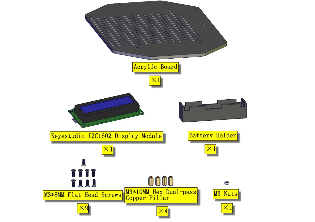
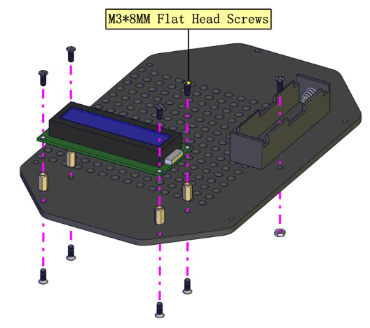
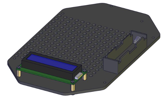
Assembling the 1602 display and battery box
Part 2
Components Needed
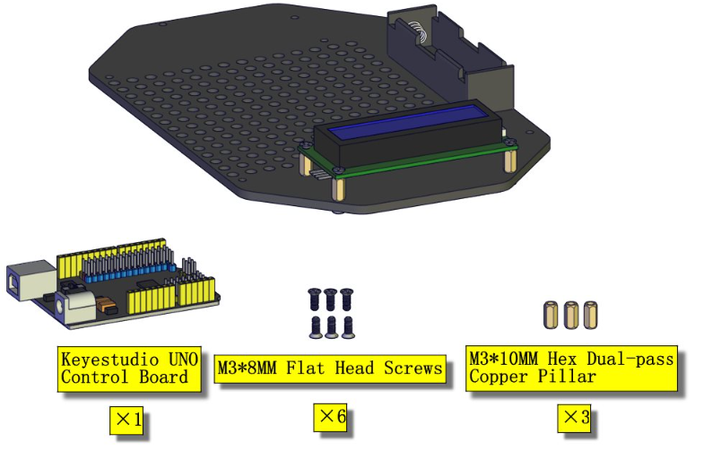
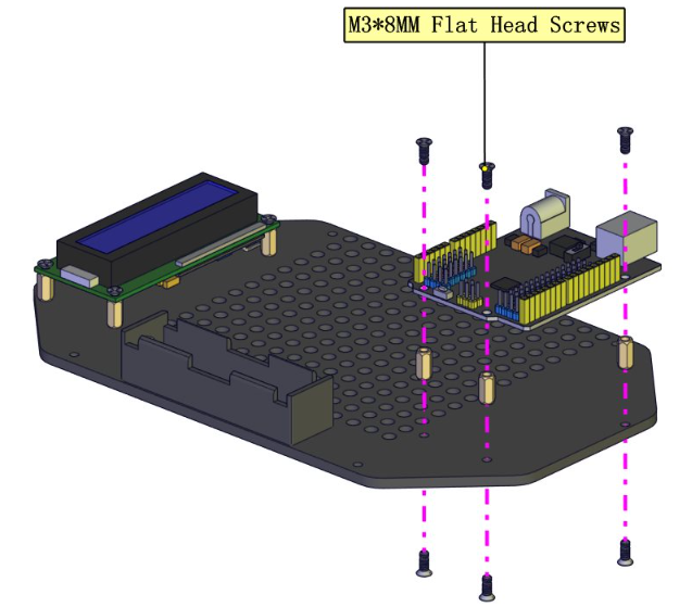
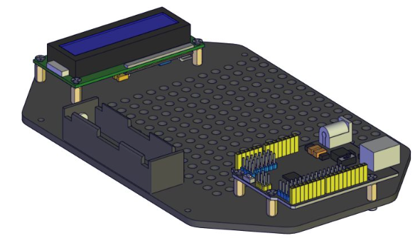
Assembling the control board
Part 3
Components Needed
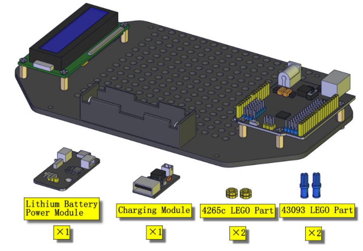
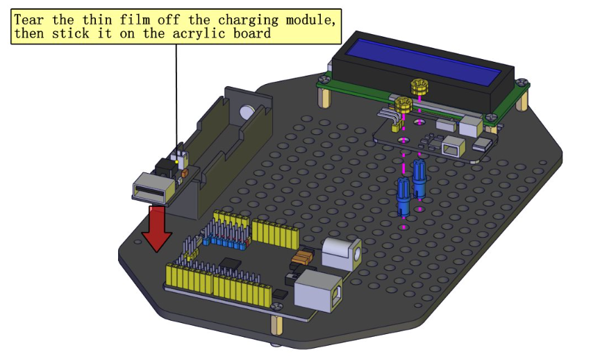
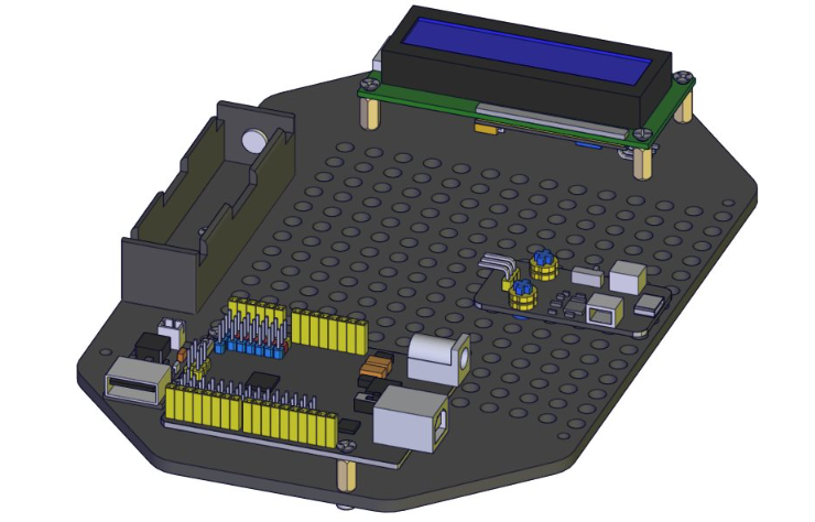
Assembling the Lithium Battery Power Module and Charging module
Part 4
Components Needed
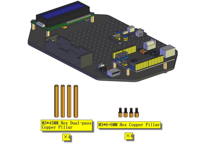
Assembling the M3*45MM Copper Columns
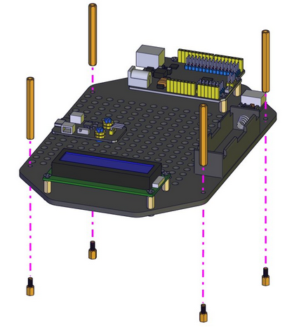
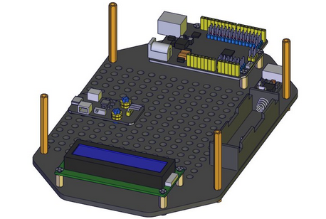
Wiring the Lower Part Of The Kit
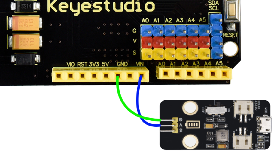
Use the 20cm M to F DuPont Wire to connect the Solar USB Charging Module to the uno control board. The G pin of the module is connected to the GND of UNO, the V pin of the module is connected to the Vin of UNO

Connect the LCD display to the UNO board
Pin Connection Table |
|
|---|---|
Pin of the LCD Display |
Pin of Control Board |
GND(black wire) |
G(GND) |
VCC(red wire) |
V(5V) |
SDA(blue wire) |
A4 |
SCL(green wire) |
A5 |
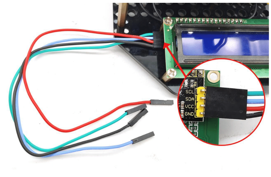
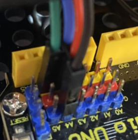
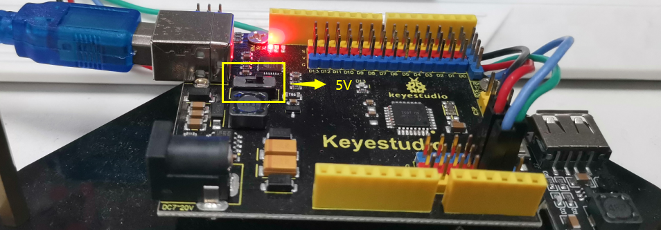
Note: The working voltage of the LCD Display is 5V, please make sure the 3.3-5V Switch on the control board is dial to 5V.
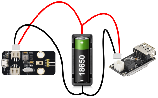
Install an 18650 battery inside the battery case, taking care that the positive and negative terminals of the battery are all the way to the positive and negative terminals of the battery case.
Connect the battery case to the solar usb charging module and mobile phone charging module.
Part 5
Components Needed
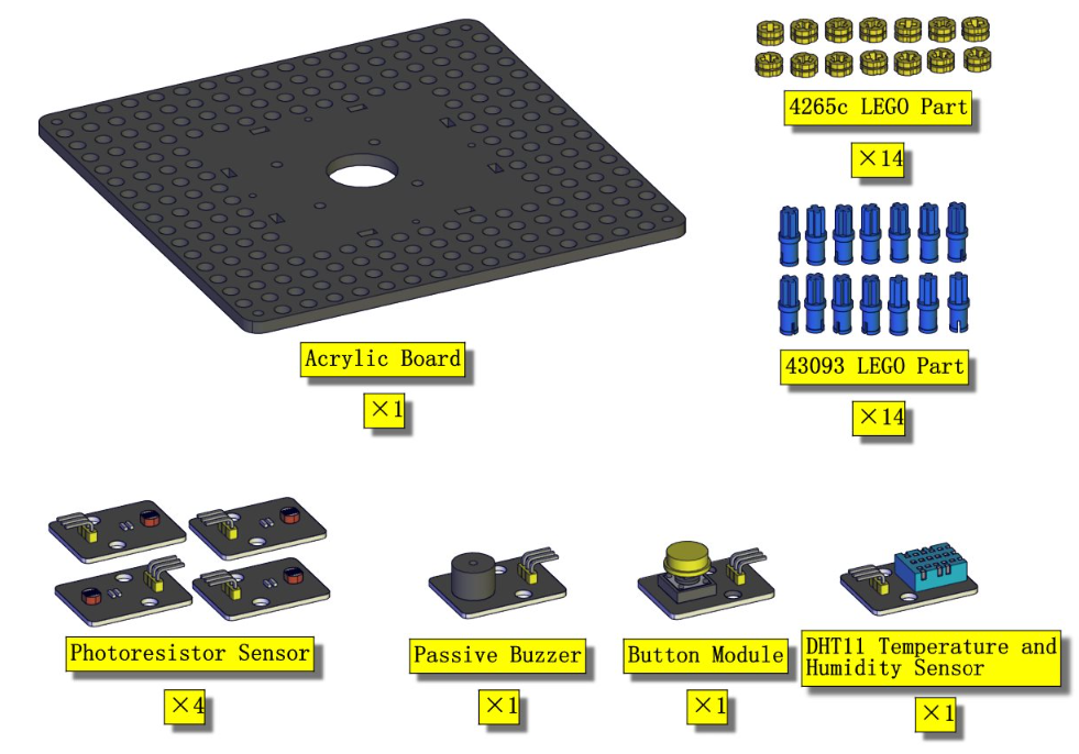
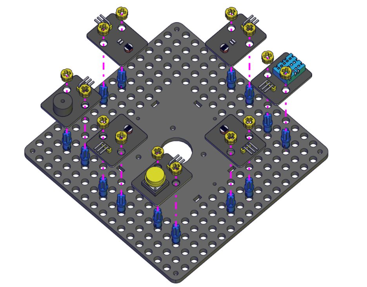
Assembling the sensors and modules
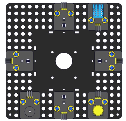
Part 6
Components Needed
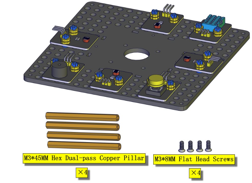
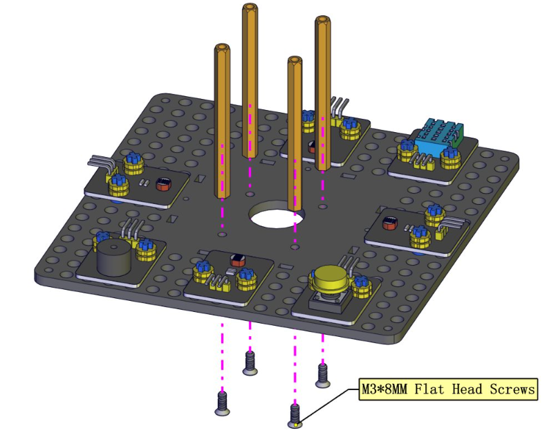
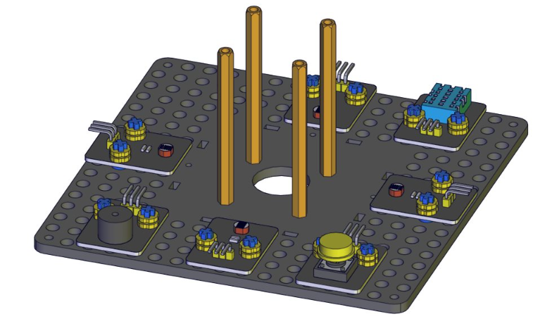
Part 7
Components Needed
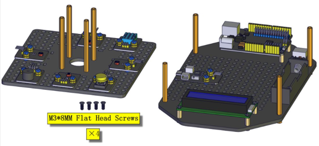
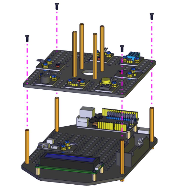
Note the orientation of the upper section, the buzzer module and the LCD display below are in the same orientation.
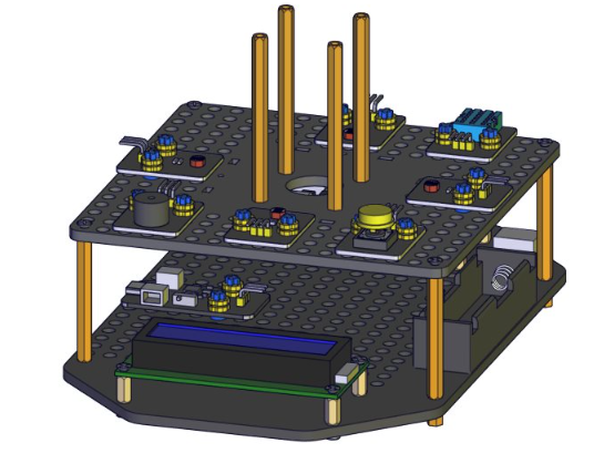
Part 8
Components Needed
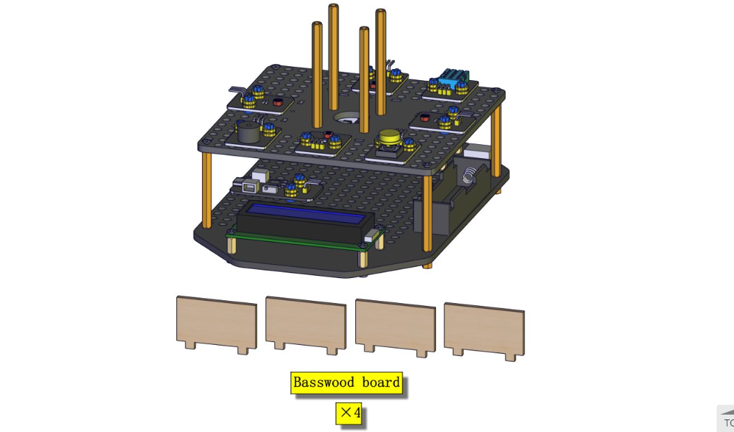
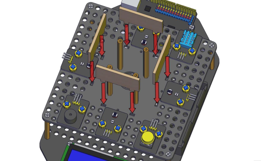
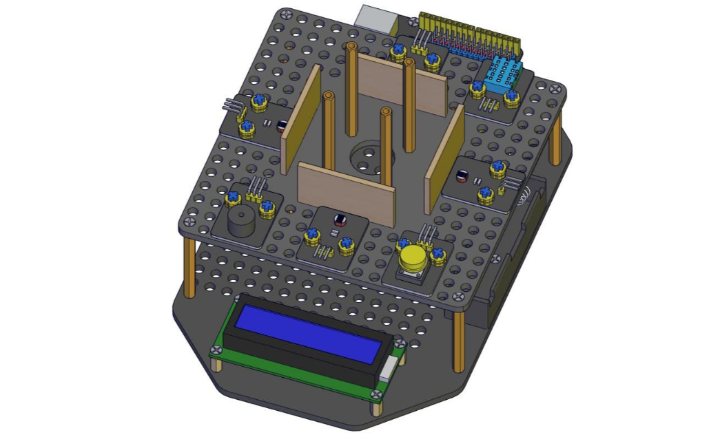
Part 9
Components Needed
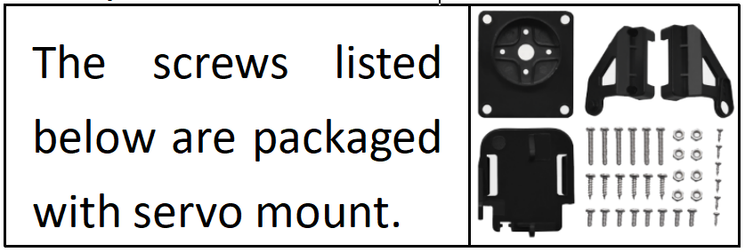
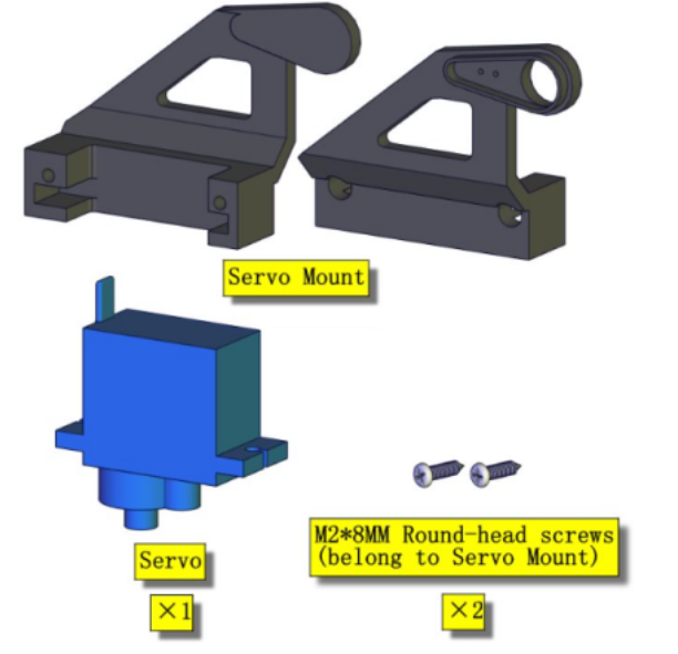
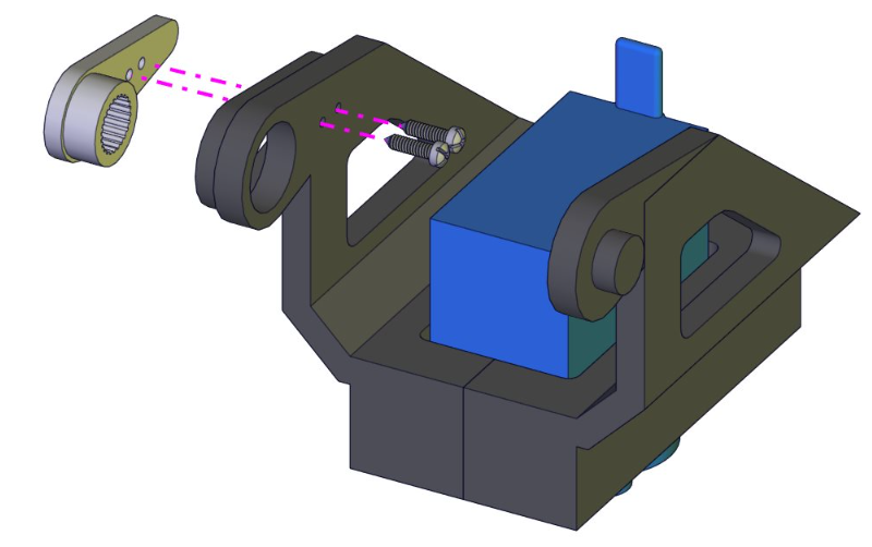
Installation Diagram (mind the installation direction of the servo)
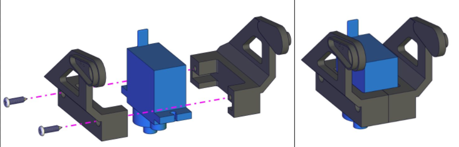
Part 10
Components Needed
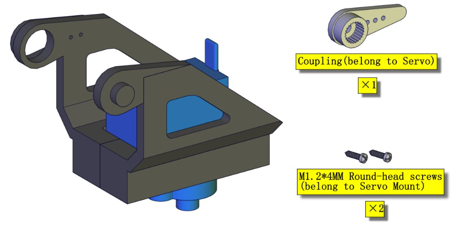
Part 11
Components Needed
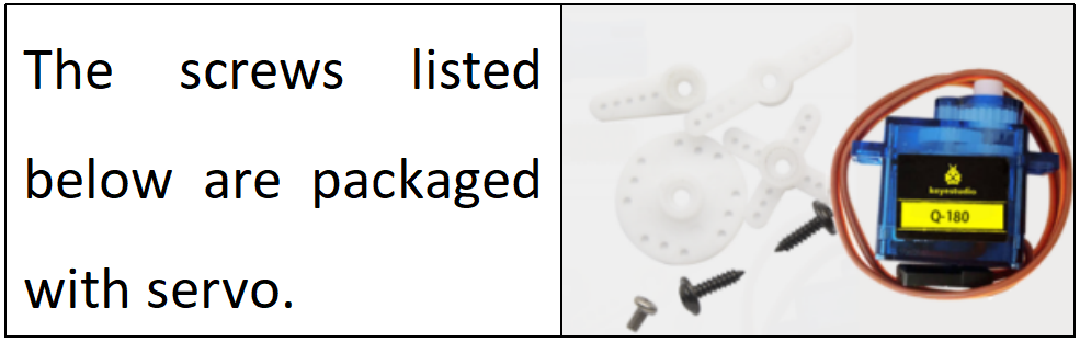
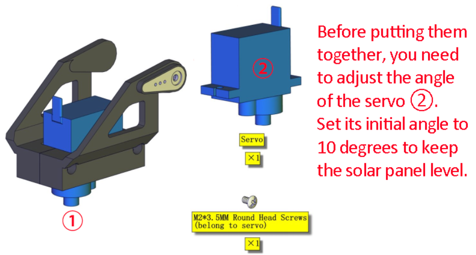
Before putting them together, you need to adjust the angle of the servo ②.Set its initial angle to 10 degrees to keep the solar panel level.
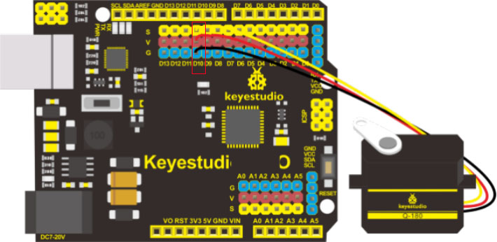
Connection Diagram
Note: The servo is connected to G (GND), V (VCC), D10. The brown wire is connected to Gnd (G), the red wire is connected to (V), and the orange wire is connected to digital pin D10.
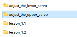
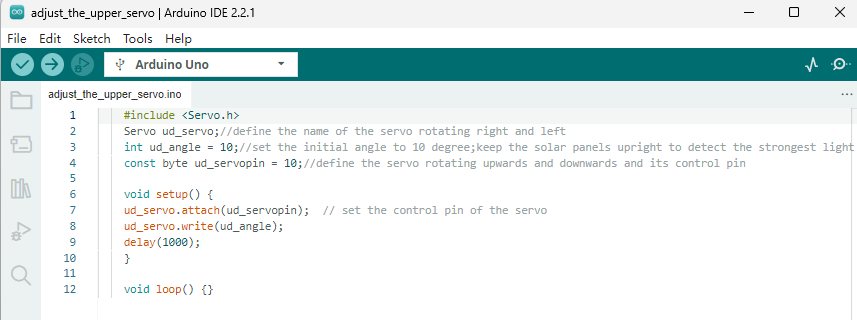
Installation Diagram (pay attention to the angle of the servo, as shown in the picture)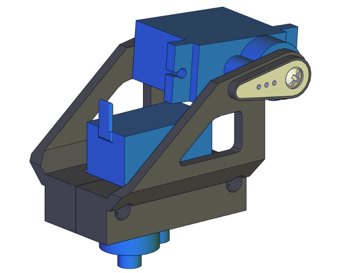
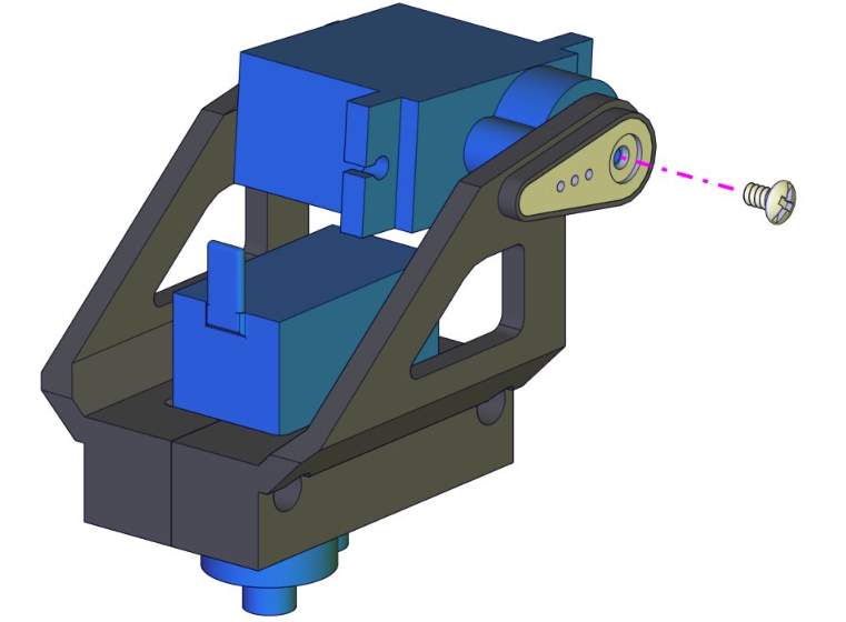
Note: You cannot turn the servo shaft until you have completed this fixing step, otherwise you will need to re-set it to 10 degree using the code above.
Part 12
Components Needed
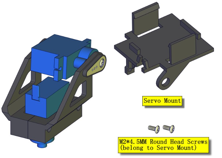
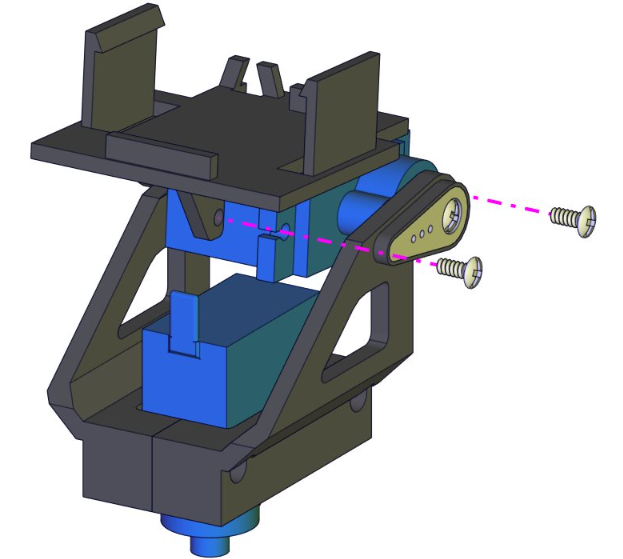
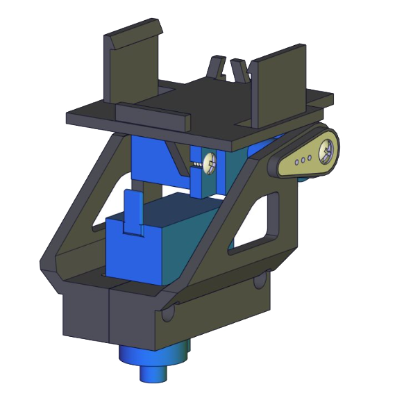
Part 13
Components Needed
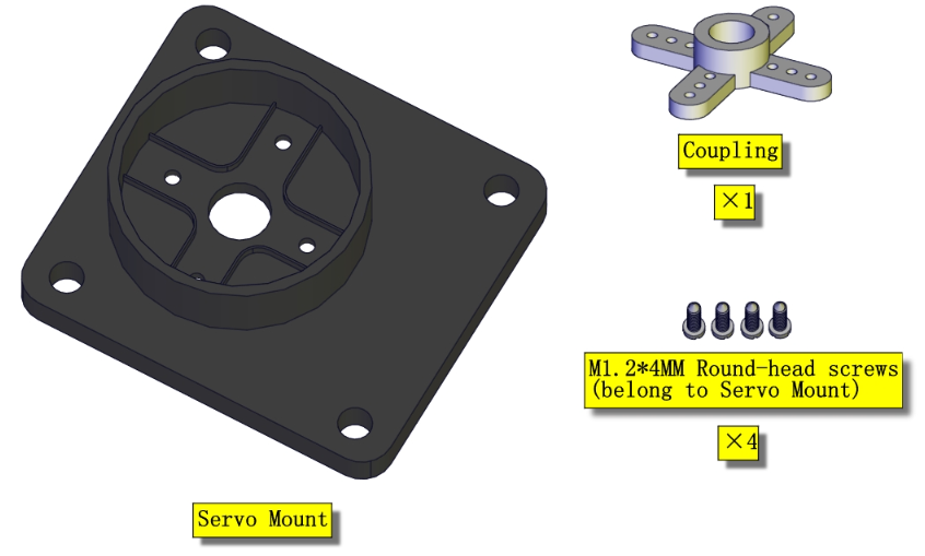
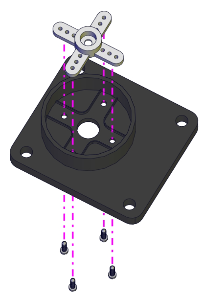
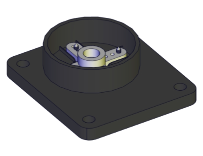
Part 14
Components Needed
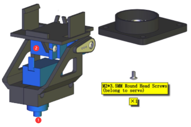
Before putting them together, you need to adjust the angle of the servo ①. Set its initial angle to 90 degrees.
Connection Diagram
Note: The servo is connected to G (GND), V (VCC), D9. The brown wire is connected to Gnd (G), the red wire is connected to (V), and the orange wire is connected to digital pin D9.
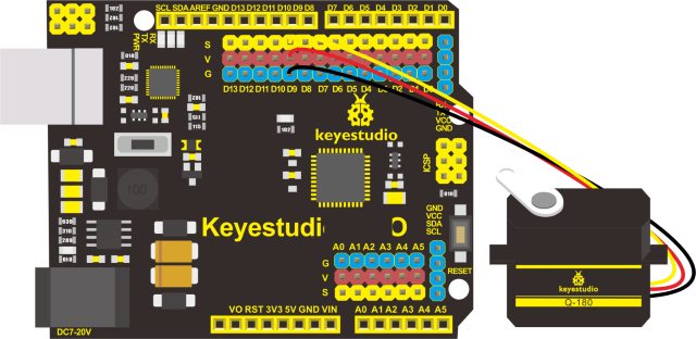
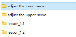
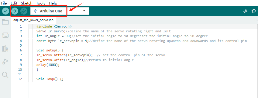
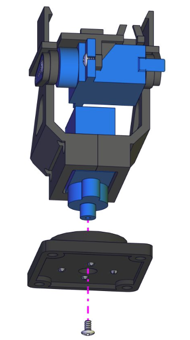
Installation Diagram
Note: You cannot turn the servo shaft until you have completed this fixing step, otherwise you will need to re-set it to 90 degree using the code above.
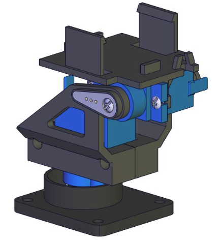
Part 15
Components Needed
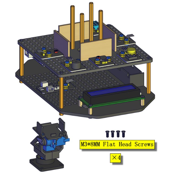
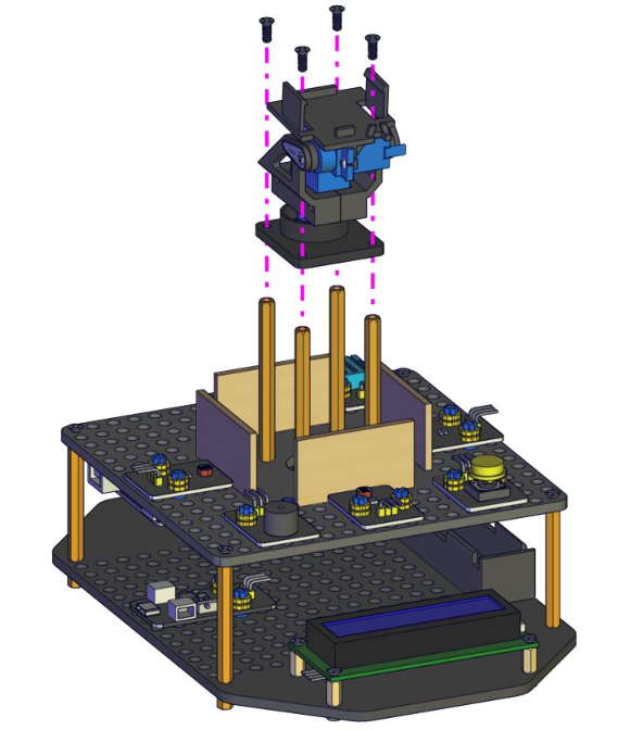
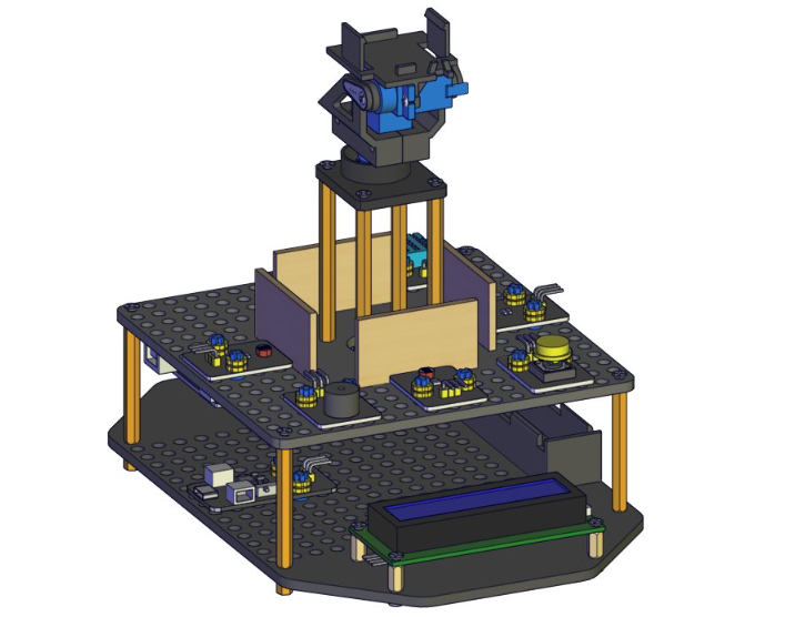
Part 16
Components Needed
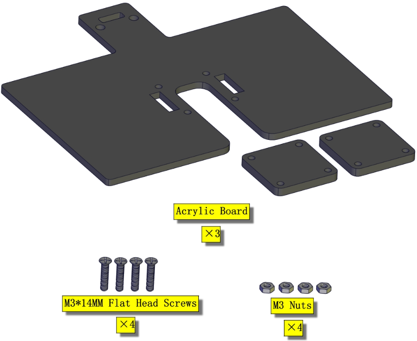
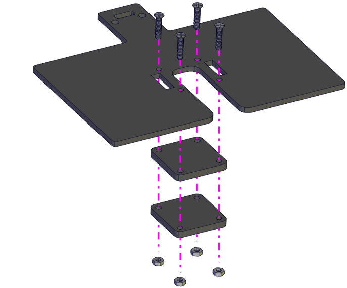
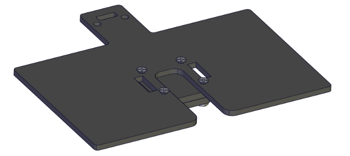
Part 17
Components Needed
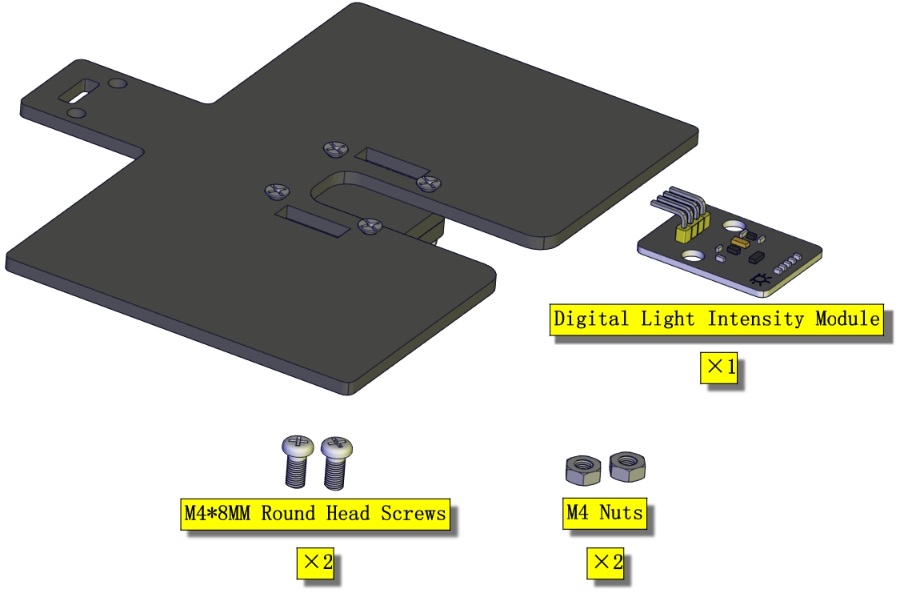
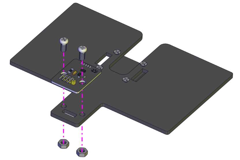
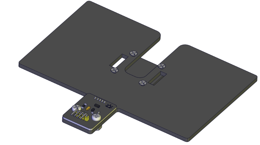
Part 18
Components Needed
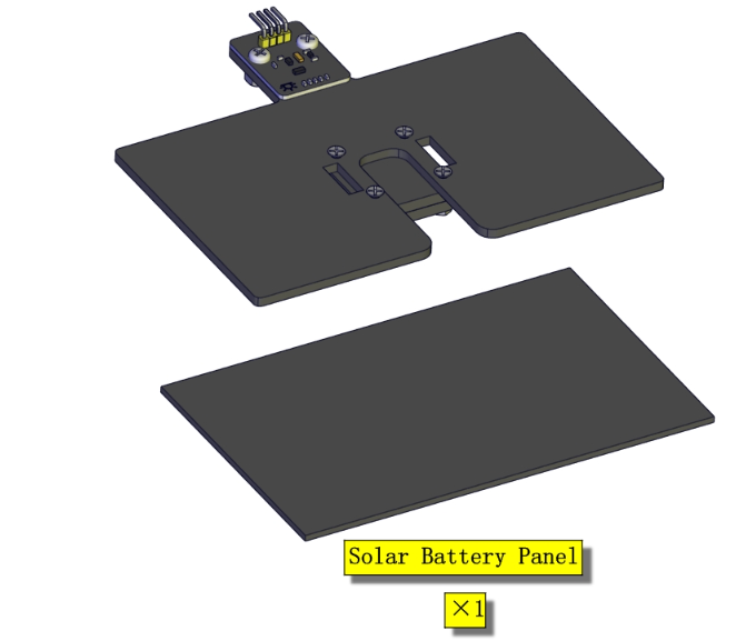
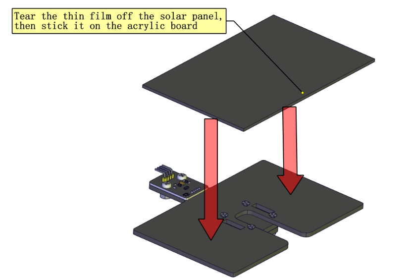
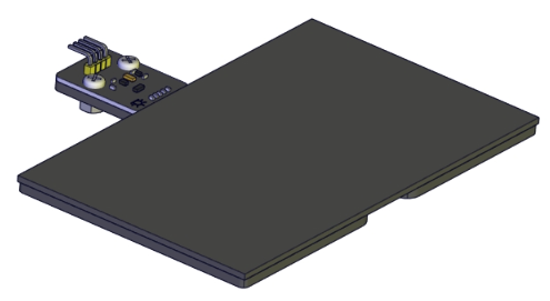
Part 19
Components Needed
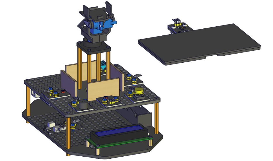
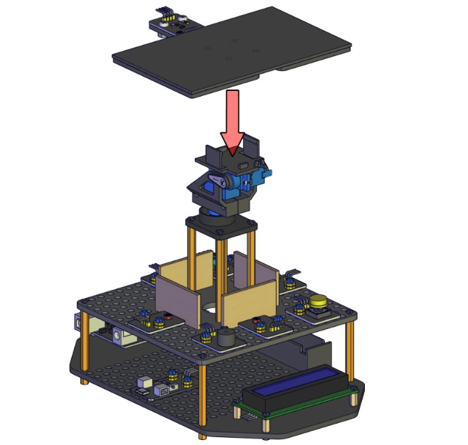
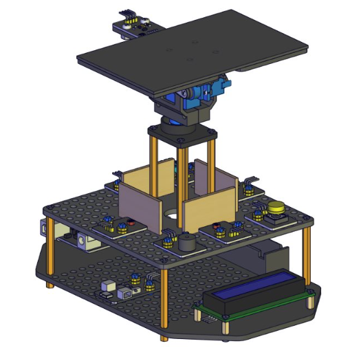
Wiring the Upper Part Of The Kit
1)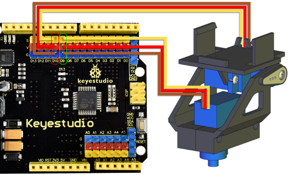 Connect the lower servo to D9 of the UNO control board, and the upper servo of D10 on the UNO control board. Connect the brown wire of the servo to G, the red wire to V, and the yellow wire to S.
2)Plug the jack of the solar panel to the SOLAR4.8-6.0V end of the solar USB charging module.
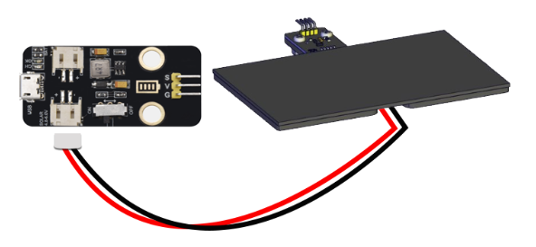
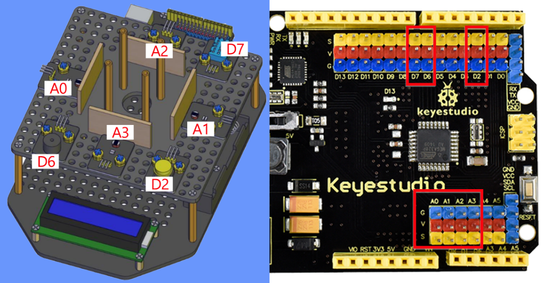
3)Next, we will use the seven 3P 26AWG 200mm F-F DuPont Wires to connect the photosensors, buzzer module, pushbutton module and the DHT11 temperature and humidity sensor to the uno board.

The photosensitive sensor on the left is connected to the A0 pin of UNO board.
The photosensitive sensor on the right is connected to the A1 pin of UNO board.
The photosensitive sensor on the back is connected to the A2 pin of UNO board.
The photosensitive sensor on the front is connected to the A3 pin of UNO board.
The button module is connected to the D2 pin of UNO board.
The buzzer module is connected to the D6 pin of UNO board.
The dht11 temperature and humidity sensor is connected to the D7 pin of UNO board.
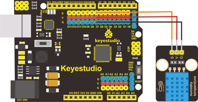
Note: In order to avoid reverse connection, we recommend wiring according to the following method:
-The G pin of the module is connected to the G pin of UNO with a black wire;
-The V pin of the module is connected to the V pin of UNO with a red wire;
-The S pin of the module is connected to the S pin of UNO with a orange wire.
As shown in the way the dht11 temperature and humidity sensor is connected to the UNO board.
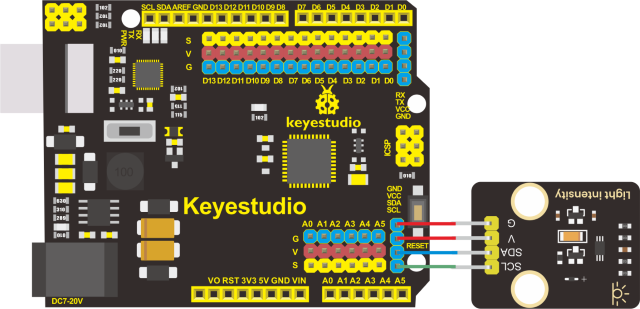
4)Finally, connect the bh1750 digital light intensity module to the UNO board.