Project 18 8*16 dot matrix-knob control
1.Project instruction
The light sensor feature that resistance is inverse proportion to to light intensity. Based on this characteristics, we made a night light. In this chapter, we will show you light column on dot matrix.
2.Project principle
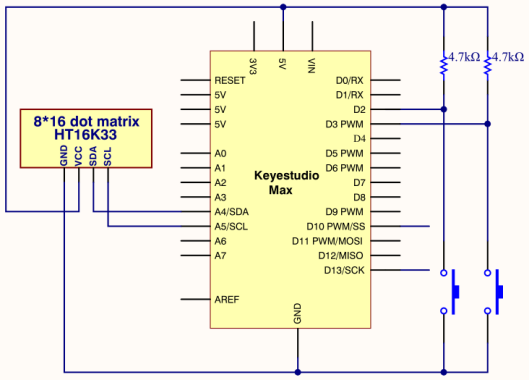
The pins of two buttons are connected to D2 and D3 and we know how to display test on 8 * 16 dot matrix. Therefore, we will make 8 * 16 dot matrix show“L” and“R”
3.Project circuit
4.Project code
Note: before uploading the code, you need to import the library files; otherwise, the code upload will fail.
#include <Wire.h>
#include "Keyestudio_LEDBackpack.h"
#include "Keyestudio_GFX.h"
Keyestudio_8x16matrix matrix = Keyestudio_8x16matrix();
int K1=3;
int K2=2;
int x;

void setup()
{
 matrix.begin(0x70);  // pass in the address
  pinMode(K1,INPUT);
  pinMode(K2,INPUT);
  matrix.drawCircle(3,8, 3, LED_ON);
  matrix.writeDisplay();  // write the changes we just made to the display
}

void loop()
{
  int K1_level=digitalRead(K1);
  int K2_level=digitalRead(K2);
  if(K1_level==0)
  {
      matrix.setTextSize(1);
      matrix.setTextWrap(false);  // we dont want text to wrap so it scrolls nicely
      matrix.setTextColor(LED_ON);
      matrix.setRotation(1);
      matrix.clear();
      matrix.setCursor(2,0);
      matrix.print("L");
      matrix.writeDisplay();
  }
  if(K2_level==0)
  {
      matrix.setTextSize(1);
      matrix.setTextWrap(false);  // we dont want text to wrap so it scrolls nicely
      matrix.setTextColor(LED_ON);
      matrix.setRotation(1);
      matrix.clear();
      matrix.setCursor(9,0);
      matrix.print("R");
      matrix.writeDisplay();
  }
}
5.Project results
After the wiring-up, open Arduino IDE and download code. The control board shows the following picture.
The dot matrix of control board shows letter O. However, the left dot matrix will show letter“L”when left button is pressed; on the contrary, the right dot matrix will display letter“R”.