4.3.8 Motor Driving and Speed Control
4.3.8.1 Introduction
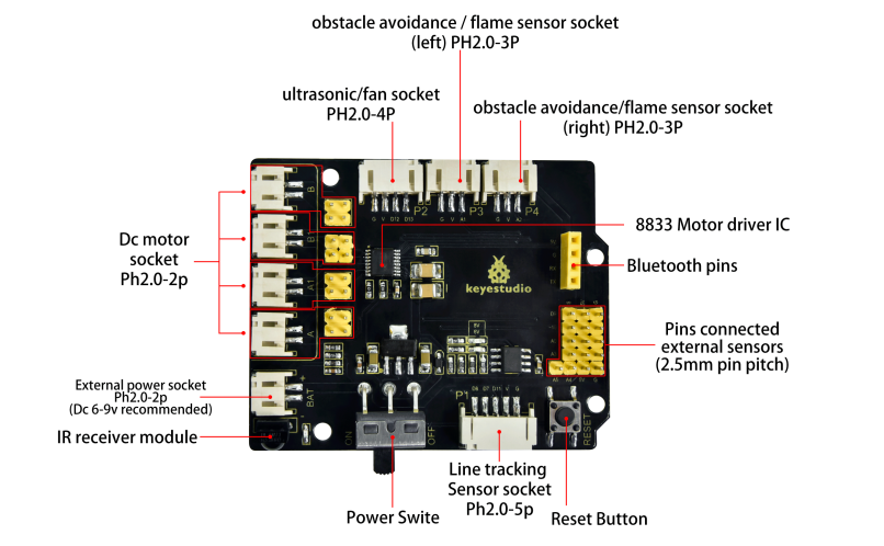
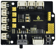
The 8833 motor driver expansion board uses PH2.0 terminals and an 8833 motor driver chip driven by the two-channel H bridge whose the largest current can be up to be 1.5A. It also integrates an IR receiver, ultrasonic sensor ports, analog ports, line tracking interfaces and pin headers for BT wifi and servo drivers
4.3.8.2 Component Knowledge
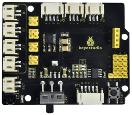
Keyestudio 8833 motor driver expansion board
Parameter:
Logic part input voltage: DC 5V
Input voltage of driving part: DC 6-9 V
Logic part operating current: <36mA
Operating current of driving part: <2A
Maximum power dissipation: 25W (T=75℃)
Control signal input level: high level 2.3V<Vin<5V, low level -0.3V<Vin<1.5V
Working temperature: -25+130℃
4.3.8.3 Drive Robot to Move
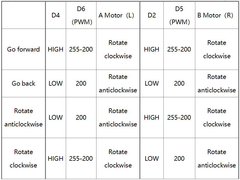
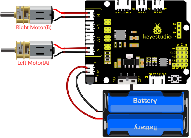
From the above diagram, it is known that the direction pin of B motor is D2; a speed pin is D5; D4 is the direction pin of A motor; and D6 is speed pin. PWM drives the robot car. The PWM value is in the range of 0-255. The larger the number, the faster the rotation of the motor.
4.3.8.4 Components
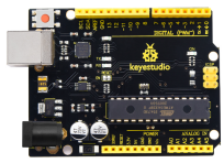
Keyestudio 4.0 development board *1 |
Keyestudio 8833 motor driver expansion board *1 |
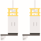
Motor*1 |
|---|---|---|
|
|
|
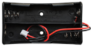
18650 Battery Holder*1 |
2P Dupont Wire*2 |
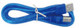
USB cable*1 |
|
|
|

4.3.8.5 Wiring Diagram
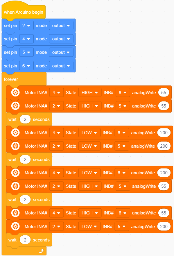
4.3.8.6 Test Code
4.3.8.7 Test Result
Upload code, power on the external power and turn the DIP switch to O. The turtle car will go for ward for 2s, back for 2s, turn left for 2s and right for 2s and stop for 2s
4.3.8.8 Extension Practice
Adjust the speed that PWM controls the motor, hook up in the same way.
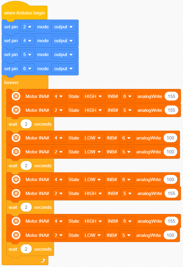
Upload code, power on the external power and turn the DIP switch to ON, do you find the motors rotate slower?
Note: low current will cause that the motor rotates slowly.