2. Product installation
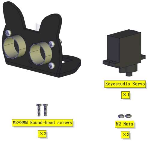
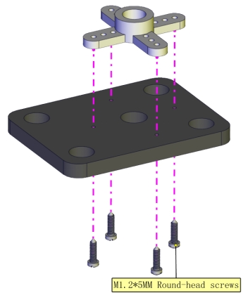
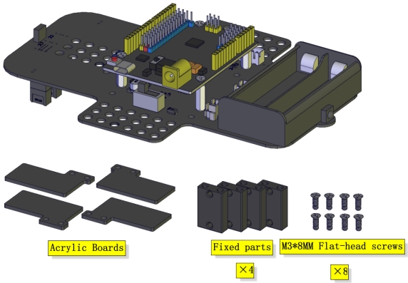
Part 1
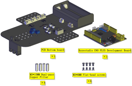
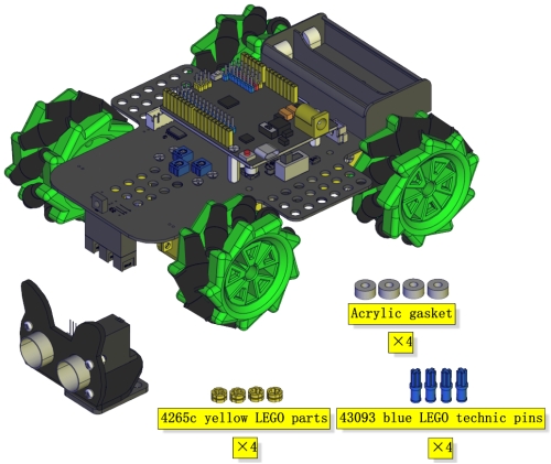
Components Needed
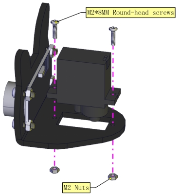
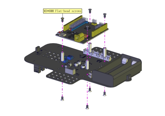
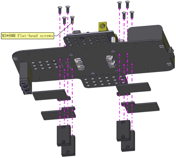
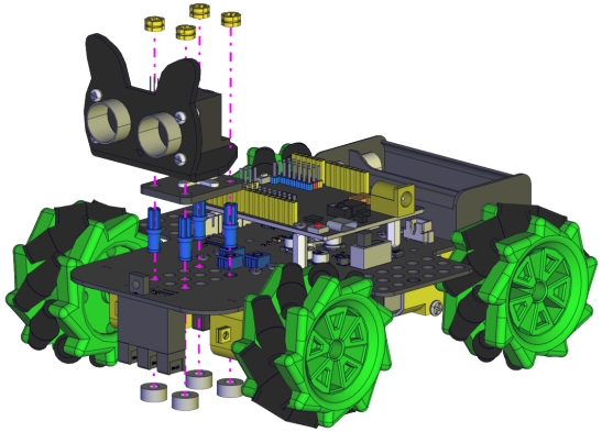
Installation Diagram
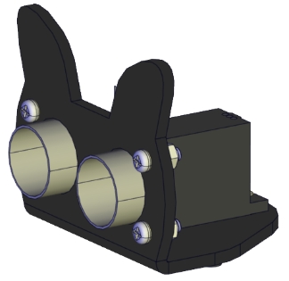
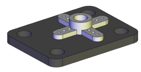
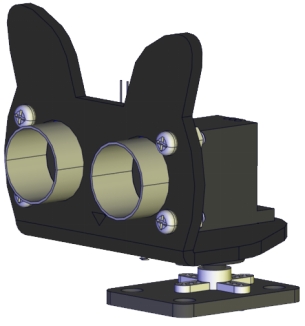
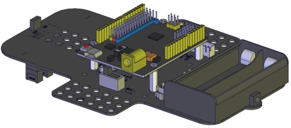
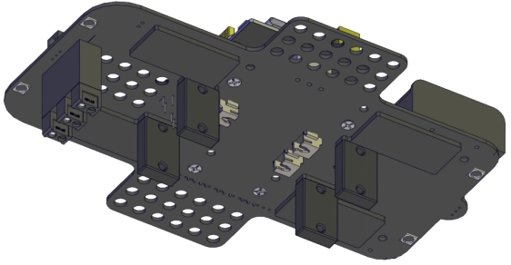
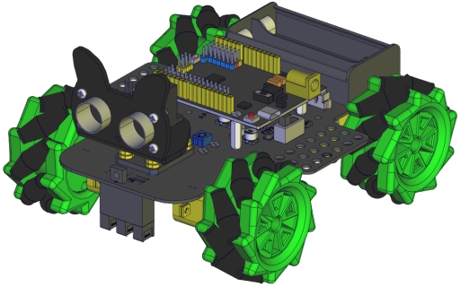
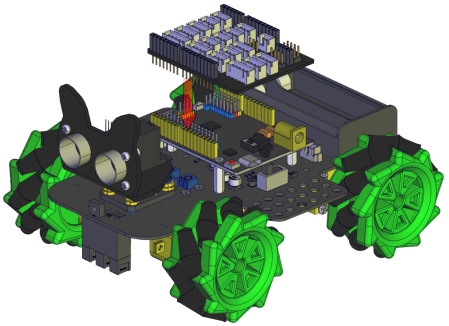
Prototype
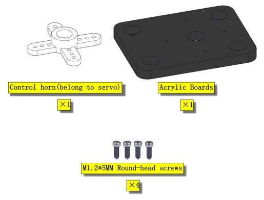
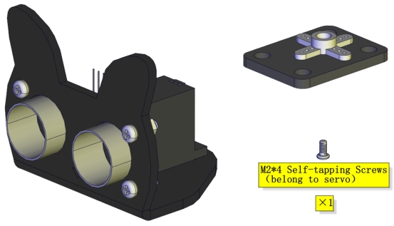
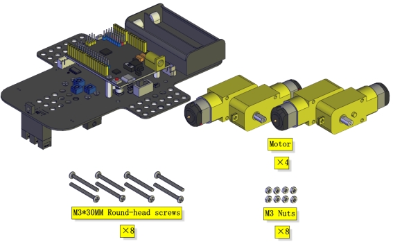
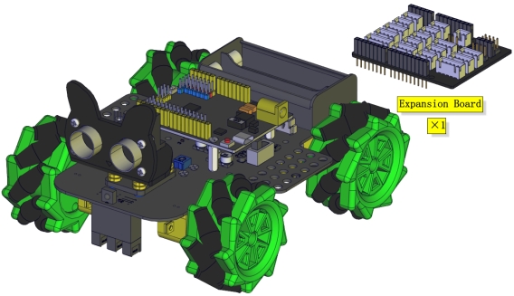
Part 2
Components Needed
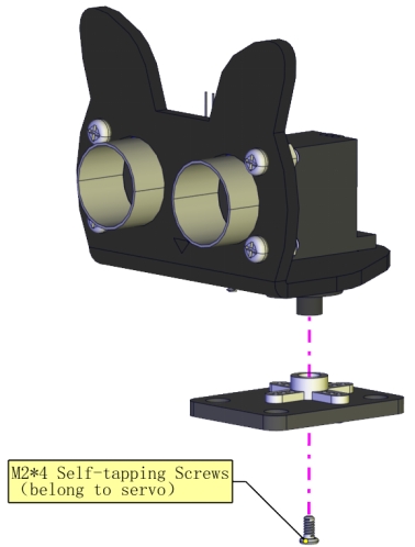
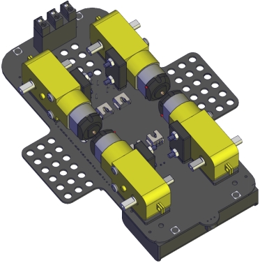
Installation Diagram
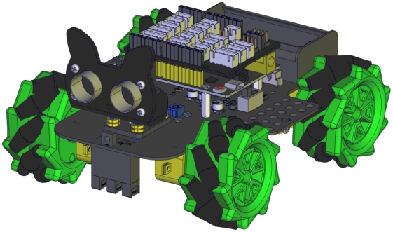
Prototype
Part 3
Components Needed
Installation Diagram
Prototype
Part 4
Set the angle of the servo to 90°
Servo |
Expansion Board |
|---|---|
Brown |
G |
Red |
5V |
Yellow |
D9 |
To adjust the code of the servo,please select it according to the course.
1.**Arduino:**Download the code file:Arduino
2.**Kidsblock:**Download the code file:Kidsblock
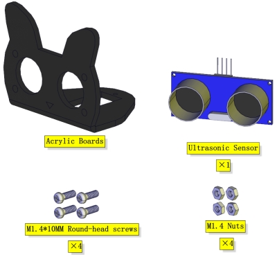
Components Needed
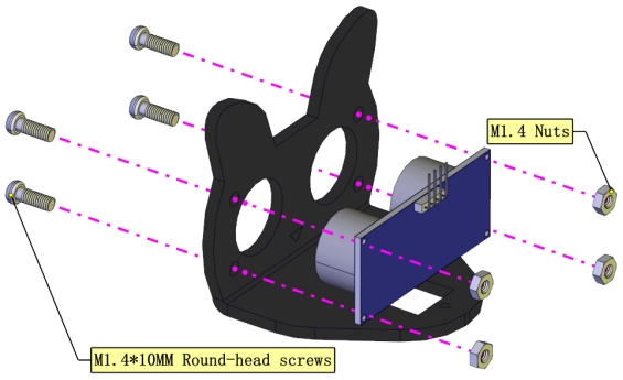
Installation Diagram(mind the installation direction)
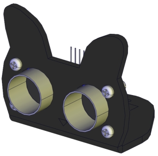
Prototype
Part 5
Components Needed
Installation Diagram
Prototype
Part 6
Components Needed
Installation Diagram
Prototype
Part 7
Components Needed
Installation Diagram(mind the direction of the motor)

Prototype
Part 8
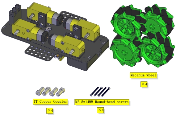
Components Needed
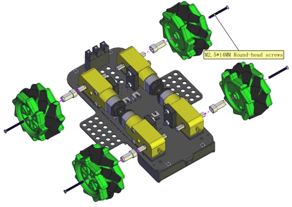
Installation Diagram
(Pay attention to the installation direction of the mecanum wheels)
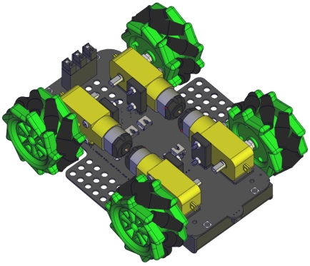
Prototype
Part 9
Components Needed
Installation Diagram
Prototype
Part 10
Components Needed
Installation Diagram
Prototype
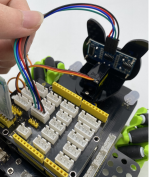
Insert a Bluetooth module
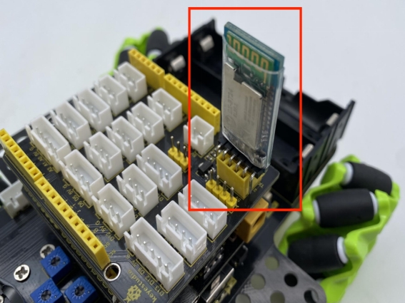
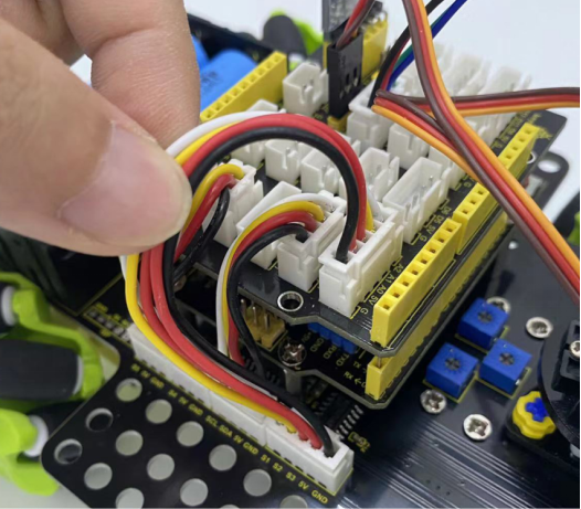
Wiring Diagram
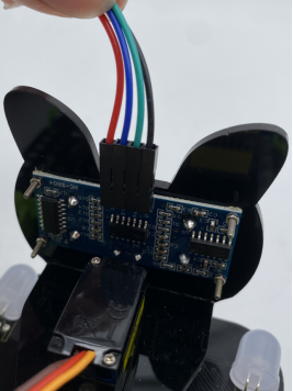
The wiring of the ultrasonic module
ultrasonic |
Sensor expansion board |
|---|---|
Vcc |
V |
Trig |
D12 |
Echo |
D13 |
Gnd |
G |
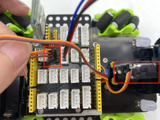
The wiring of the servo
Servo |
Sensor expansion board |
|---|---|
Brown |
G |
Red |
5V |
Orange |
D9 |
The wiring of controlling the IR receiver
Driver Board |
Expansion Board |
|---|---|
GND |
G |
5V |
5V |
S5 |
A3 |
The wiring of controlling the RGB2812 LED
Driver Board |
Expansion Board |
|---|---|
GND |
G |
5V |
5V |
S4 |
D10 |
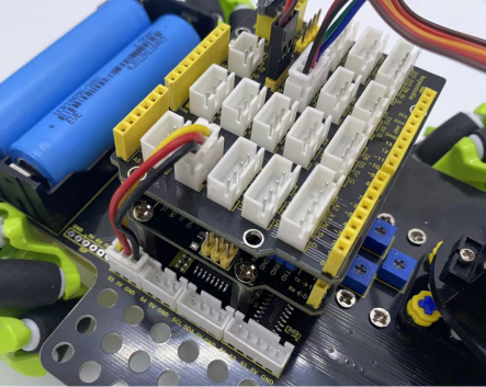
The wiring of controlling motors and 7-color LEDs
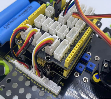
Driver Board |
Expansion Board |
|---|---|
SCL |
D2 |
SDA |
D3 |
5V |
D5 |
GND |
D4 |
The wiring of controlling the line-tracking sensor
Driver Board |
Expansion Board |
|---|---|
S1 |
A2 |
S2 |
A1 |
S3 |
A0 |
5V |
5V |
GND |
G |
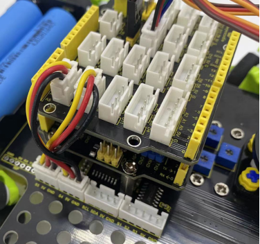
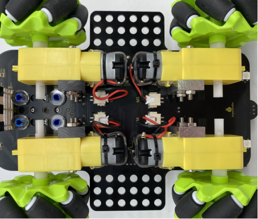
Connect the motors to the corresponding interface as shown in the figure
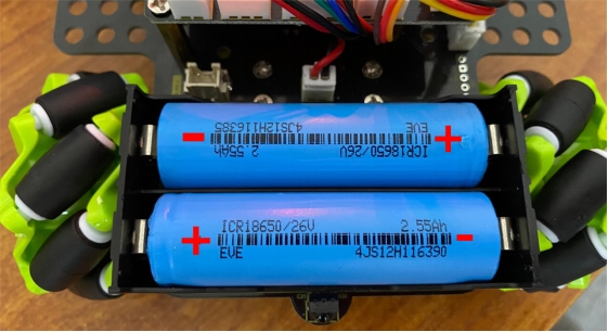
Installation of batteries