2. Product installation
After checking all the parts in this kit, we need to mount the tank robot. Let’s install the smart car in compliance with the following instructions.
Assembly Video
Note: The assembly video is provided in the
video.7zfile included in this package. Please extract it to viewvideo/KS0605.mp4.
Note: Peel the plastic film off the board first when installing smart car.
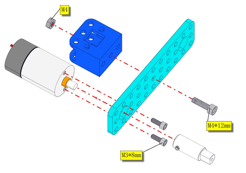
Step 1: Install Bottom Motor
Prepare the parts as follows:
M4 Nut * 2
Metal Motor *2
Metal Holder *2
Coupler *2
Blue Supportive Parts *2
M4*12MM Inner Hex Screw * 2
M1.5 Hex Key Nickel Plated Allen Wrench *1
M3 Hex Key Nickel Plated Allen Wrench *1
M2.5 Hex Key Nickel Plated Allen Wrench *1
M3*8MM Inner Hex Screw * 4
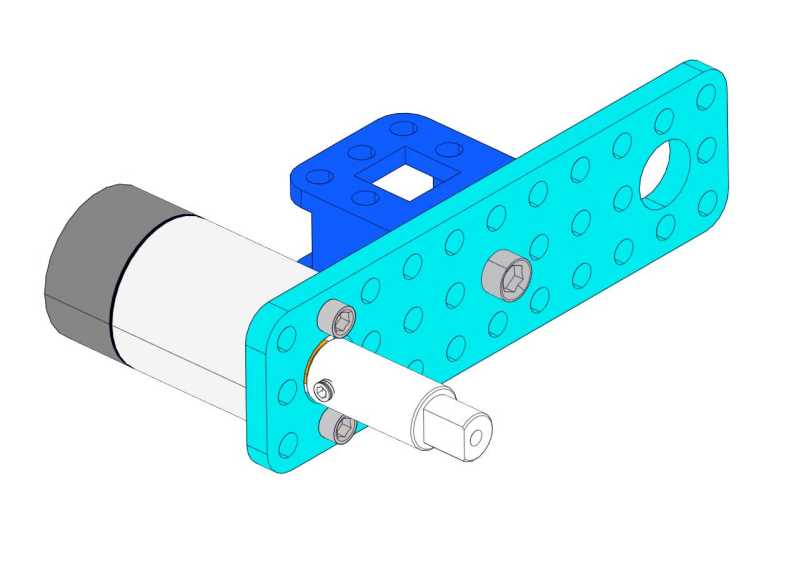
Prompt: assemble another side motor in the same way.
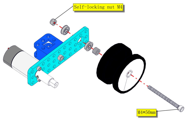
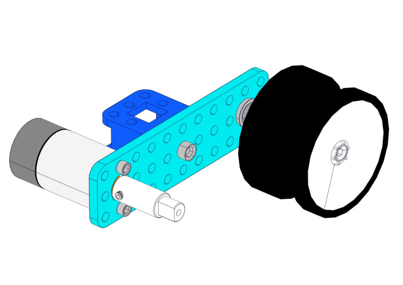
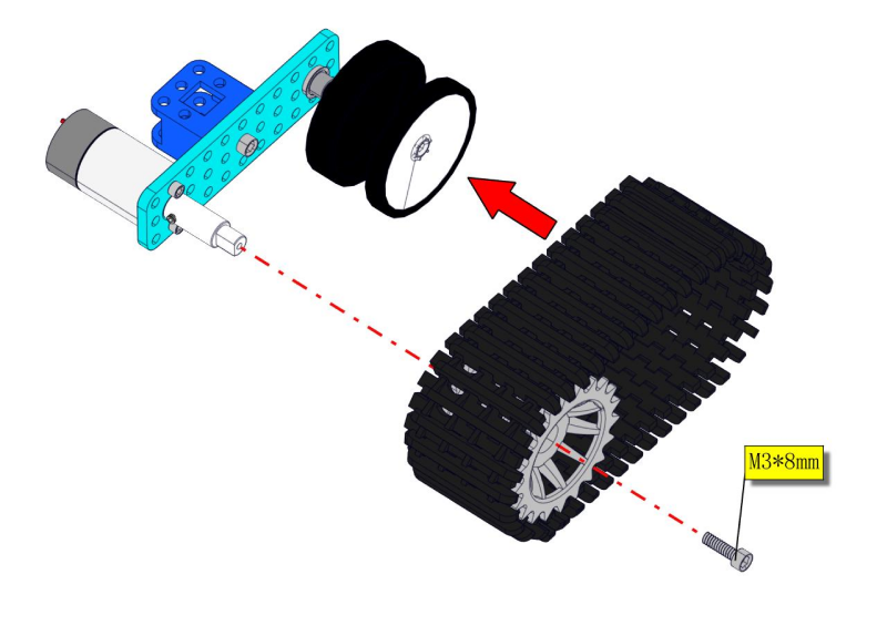
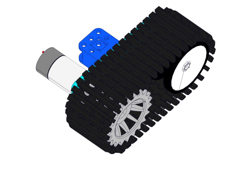
Step 2: Install Driver Wheel
Prepare the parts as follows:
M3*8MM Inner Hex Screw * 2
M4*50MM Inner Hex Screw * 2
Tank Load-bearing Wheel * 2
Flange Bearing * 4
Gasket*2
Caterpillar Band *2
M4 Self-locking Nut * 2
M3 Hex Key Nickel Plated Allen Wrench *1
M2.5 Hex Key Nickel Plated Allen Wrench *1
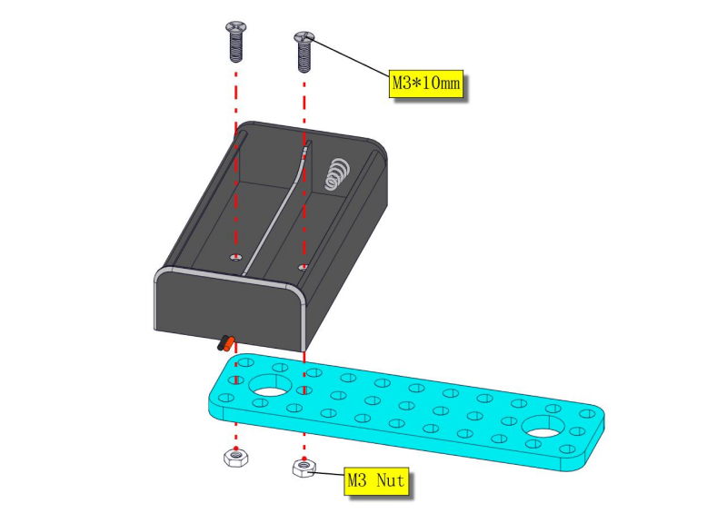
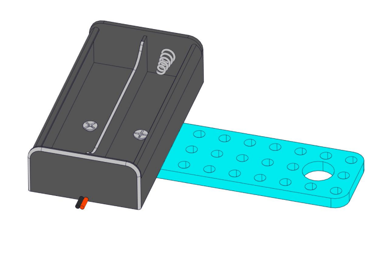
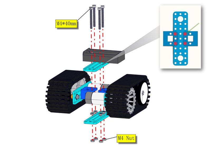
Step 3: Install the Battery Holder
Prepare the parts as follows:
Battery Holder *1
M3 Nut * 2
Blue Metal holder *2
M4 Nut *8
M3*10MM Flat Head Screw * 2
M4*40MM Inner Hex Screw *4
M2.5 Hex Key Nickel Plated Allen Wrench*1
M3 Hex Key Nickel Plated Allen Wrench *1
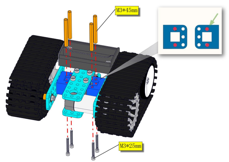
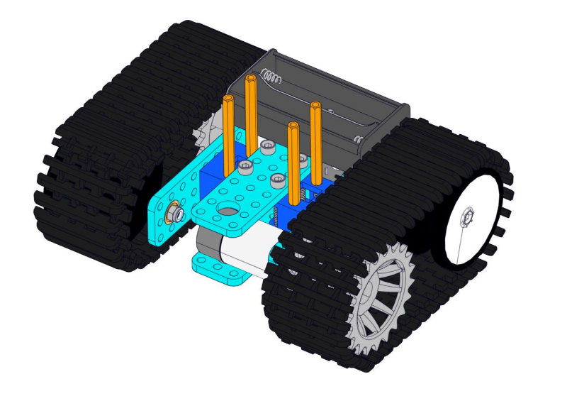
M3*25MM Inner Hex Screw *4
M3*45MM Hex Copper Pillar *4
Screwdriver
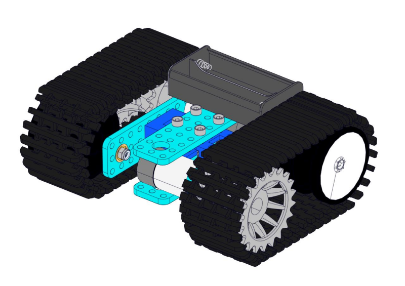
Move to fix the metal holder on the motor wheel with four M4*40MM inner hex screws and four M4 nuts when the mounting process is completed.
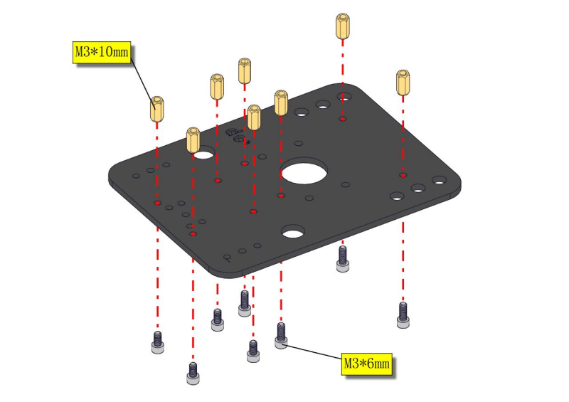
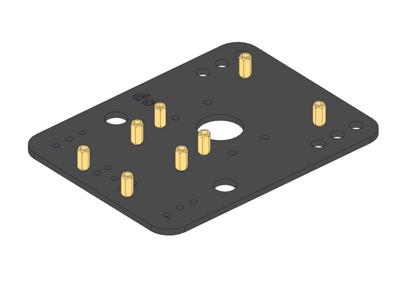
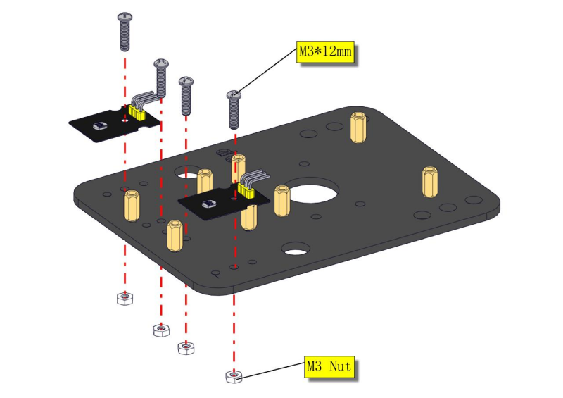
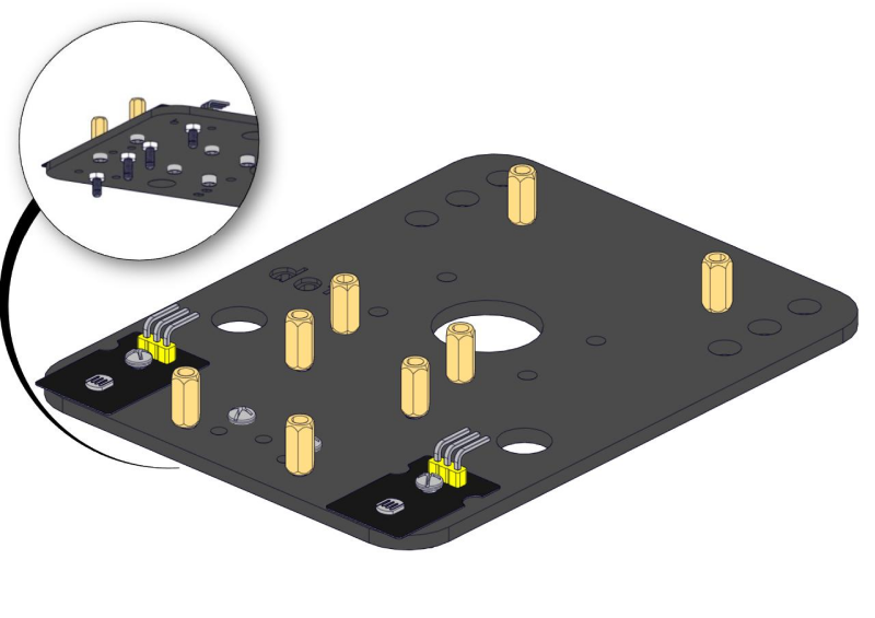
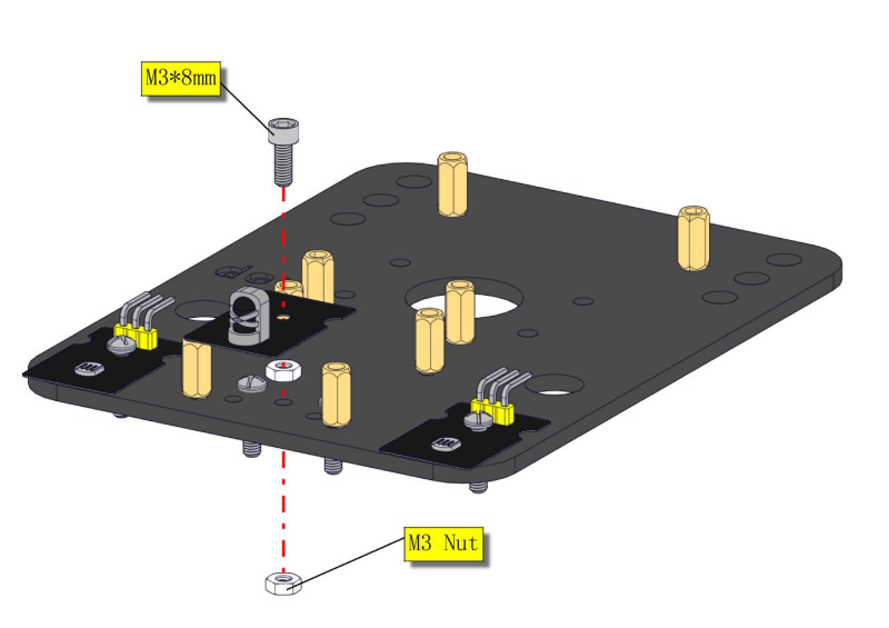
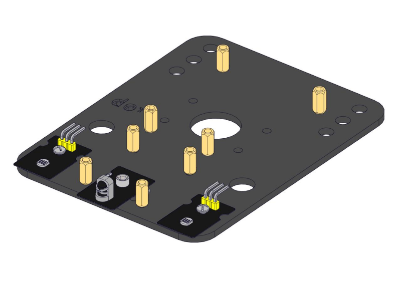
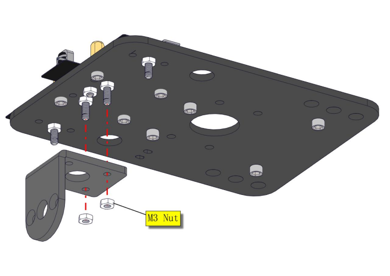
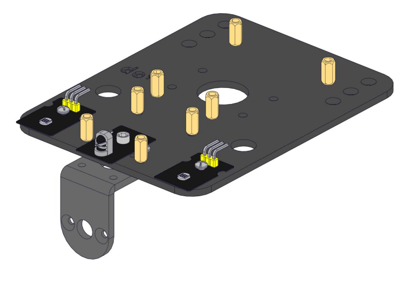
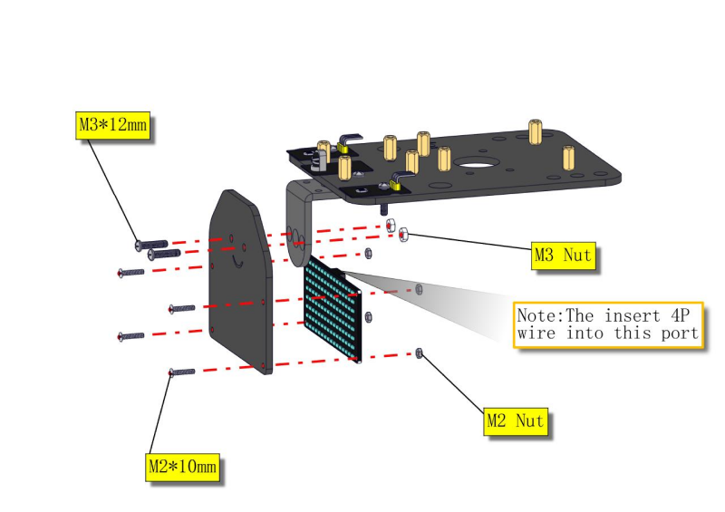
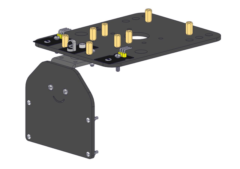
Step 4: Mount Acrylic Board and Sensors
Acrylic Board * 2
L- type Black Bracket *1
Photocell Sensor *2
IR Receiver Module *1
8X16 LED Panel *1
M2 Nut *4
M3 Nut *10
M3*6MM Inner Hex Screw * 8
M3*8MM Inner Hex Screw * 8
M2.5 Hex Key Allen Wrench *1
M3*12MM Round Head Screw *6
M3*10MM Hexagon Copper Bush *8
M2*10MM Round Head Screw * 4
Screwdriver
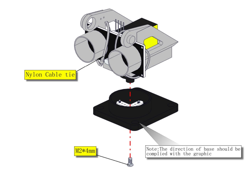
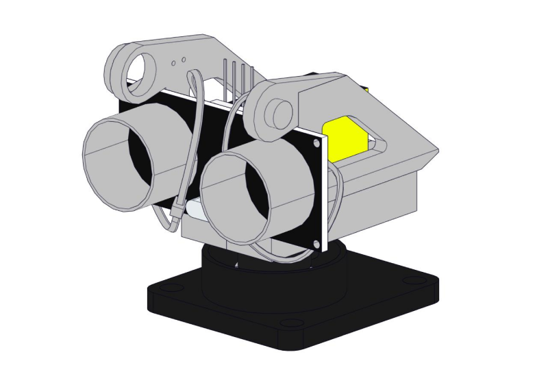
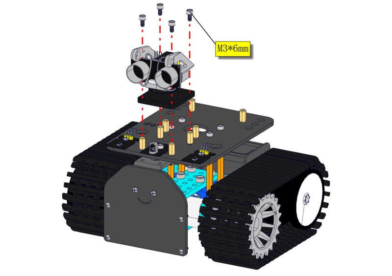
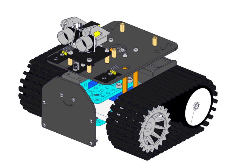
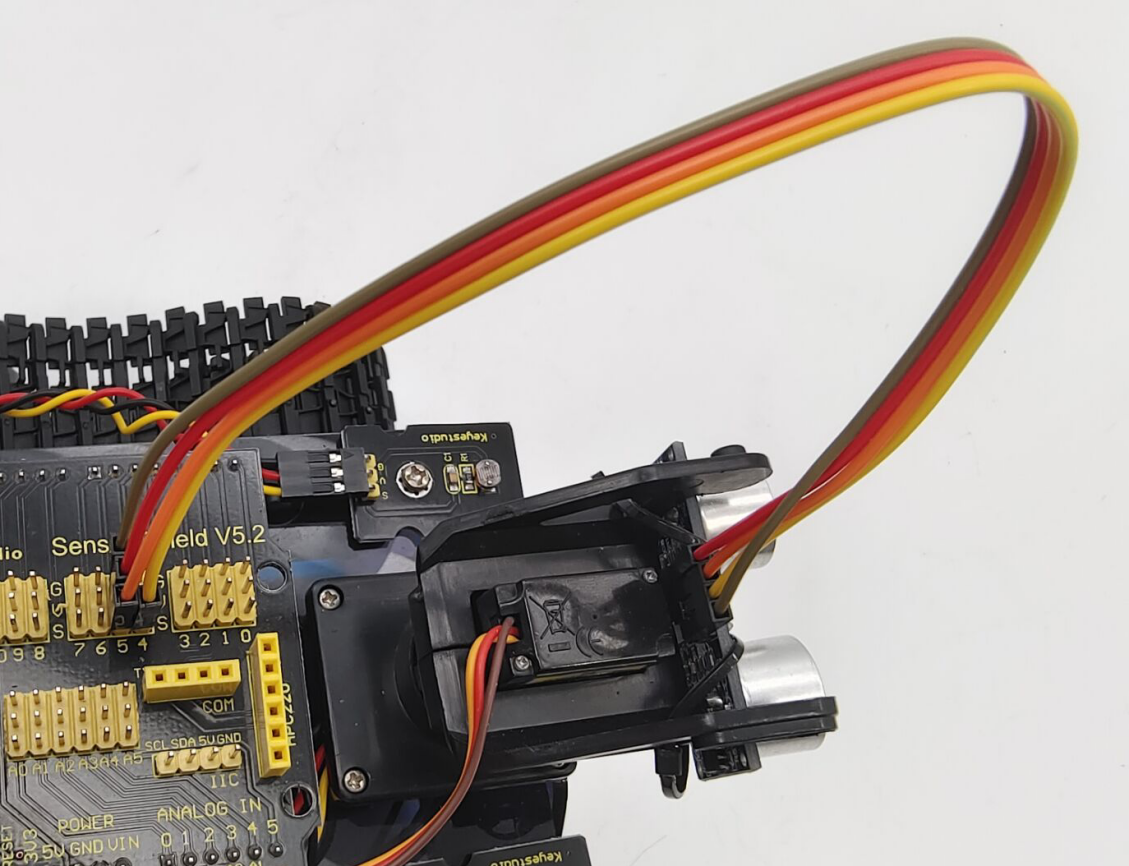
Step 5: Install the Servo Platform
Prepare the parts as follows:
Servo *1
Black Gimbal *1
Cable Tie *2
M2x8 Round Head Cross Tapping Screw *2
Ultrasonic Sensor *1
M2*4 Screw *1
M1.2*5 Screw *4
Screwdriver
**Note: **for convenient debugging, keep the ultrasonic module straight ahead and the angle of servo motor at 90°. Therefore, we need to set the servo to 90° before installing the servo platform.
Set the 90-degree code,Copy the code and upload it to the development board. The steering gear connected to port D9 will rotate to 90 °.
To upload code, you will need the Arduino IDE. Please first install the Arduino IDE by following sections 4.2–4.4. (Software Download, Set Up Arduino IDE, and Add Library)
#define servoPin 9 //servo Pin
int pos; //the angle variable of servo
int pulsewidth; // pulse width variable of servo

void setup()
{
    pinMode(servoPin, OUTPUT); //set servo pin to OUTPUT
    procedure(0); //set the angle of servo to 0°
}

void loop()
{
	procedure(90); // tell servo to go to position in variable 90°
}

// function to control servo
void procedure(int myangle)
{
    pulsewidth = myangle * 11 + 500; //calculate the value of pulse width
    digitalWrite(servoPin,HIGH);
    delayMicroseconds(pulsewidth); //The duration of high level is pulse width
    digitalWrite(servoPin,LOW);
    delay((20 - pulsewidth / 1000)); // the cycle is 20ms, the low level last for the rest of time
}
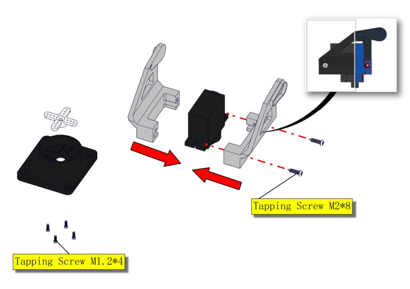
**Note: **You can find M1.2*5 Screws inside the bag of Plastic Platform.
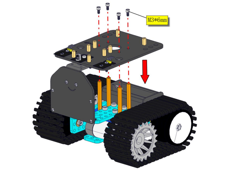
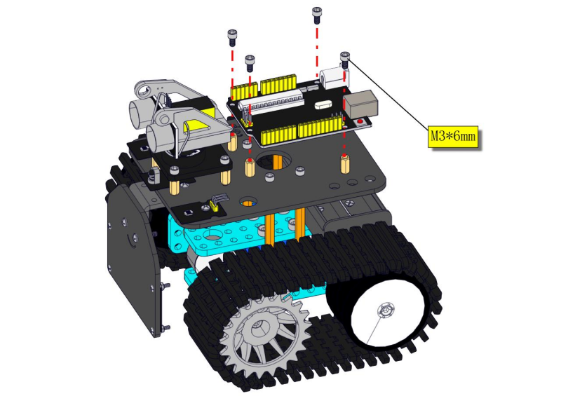
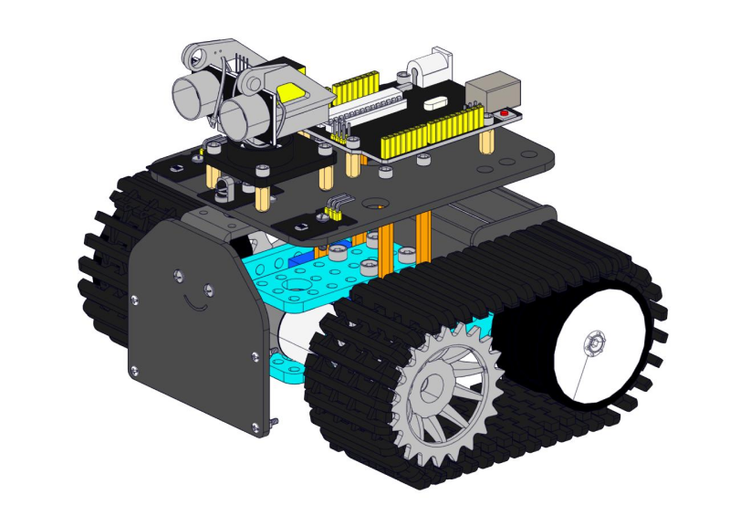
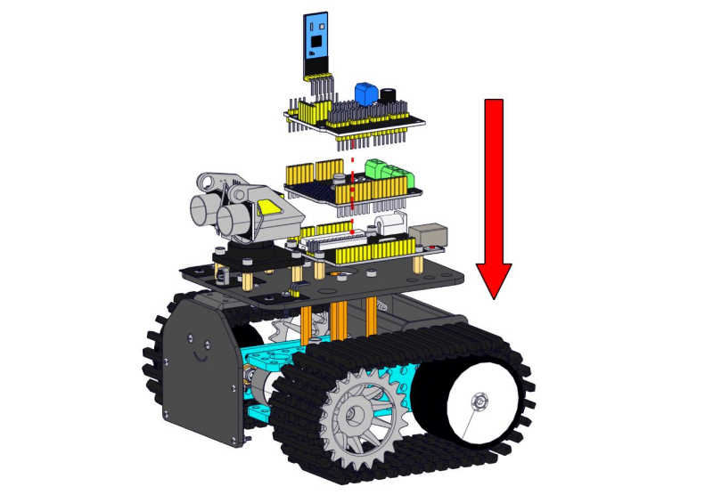
Step 6: Install Sensors and Boards
Prepare the parts as follows:
M3*6MM Round Head Screw *12
L298P Shield *1
V4.0 Board *1
V5 Sensor Shield *1
Screwdriver *1
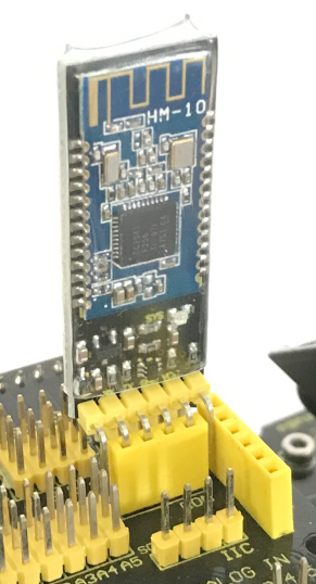
Bluetooth Module *1
M2.5 Hex Key Nickel Plated Allen Wrench *1
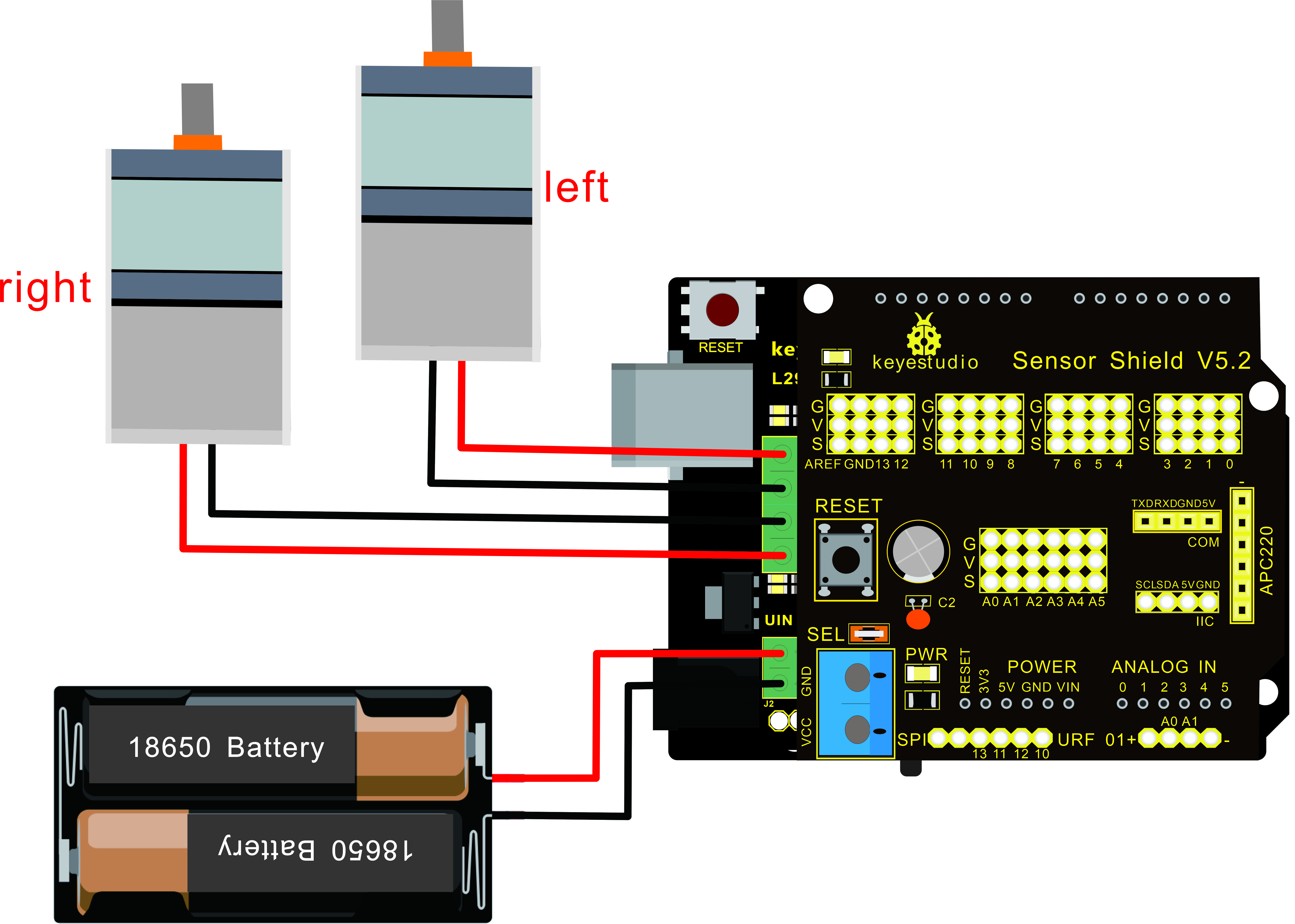
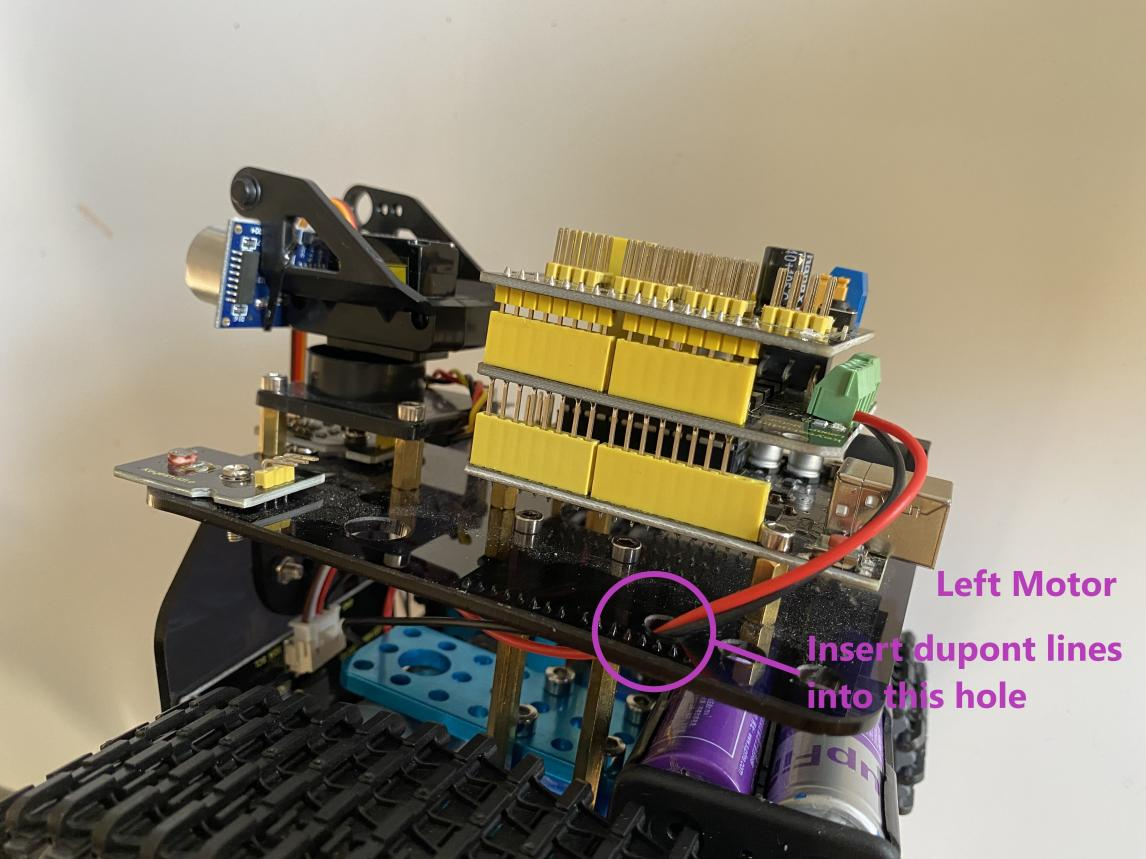
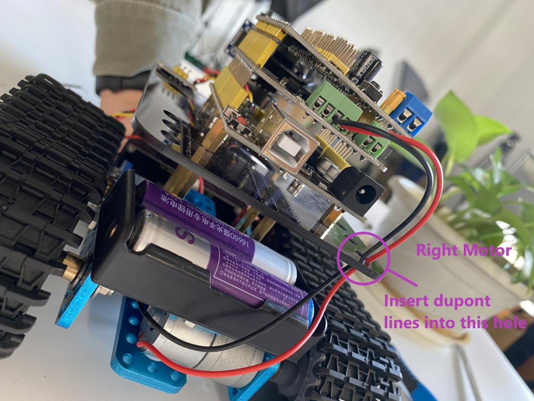
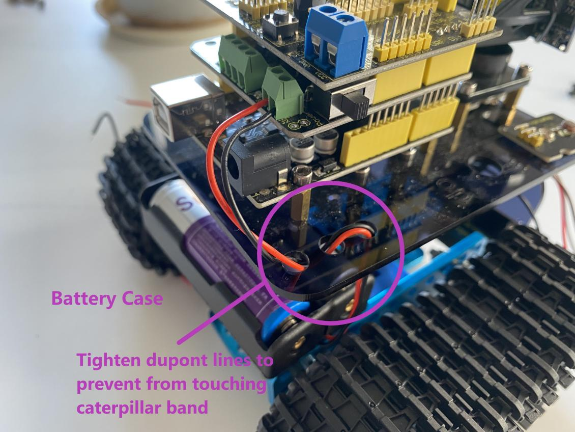
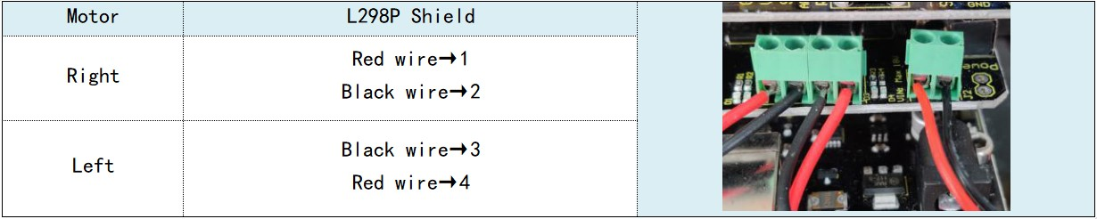
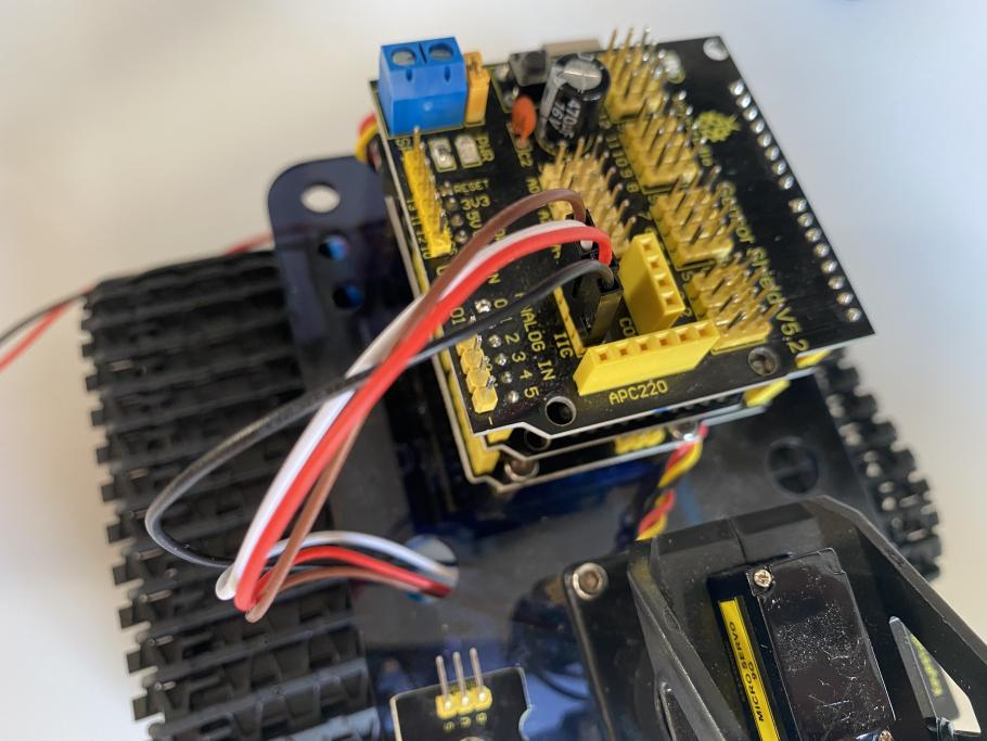
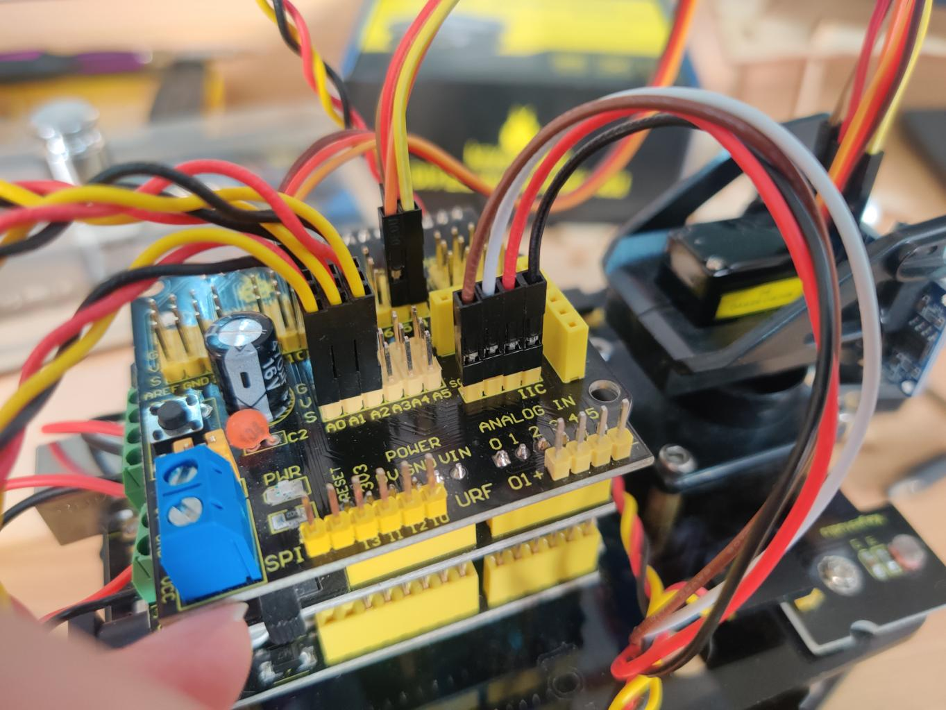
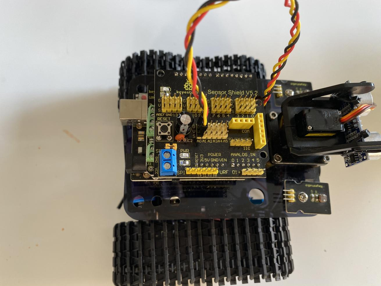
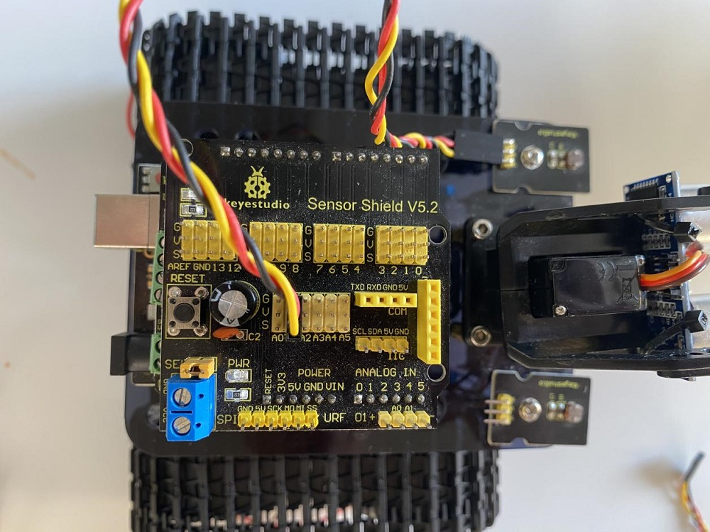
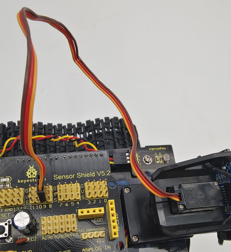
Step 7: Hook-up Guide
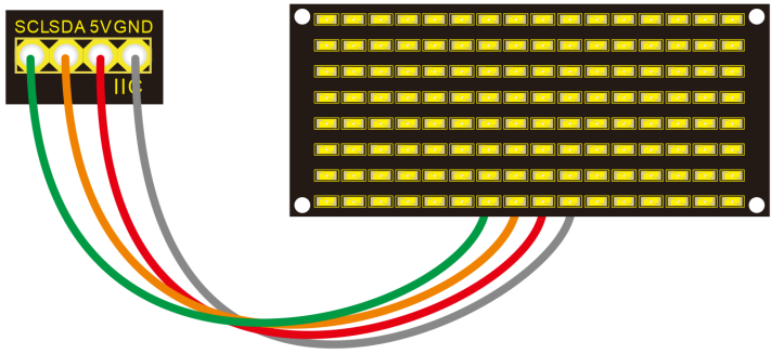
Step 8: Wire Up LED Panel
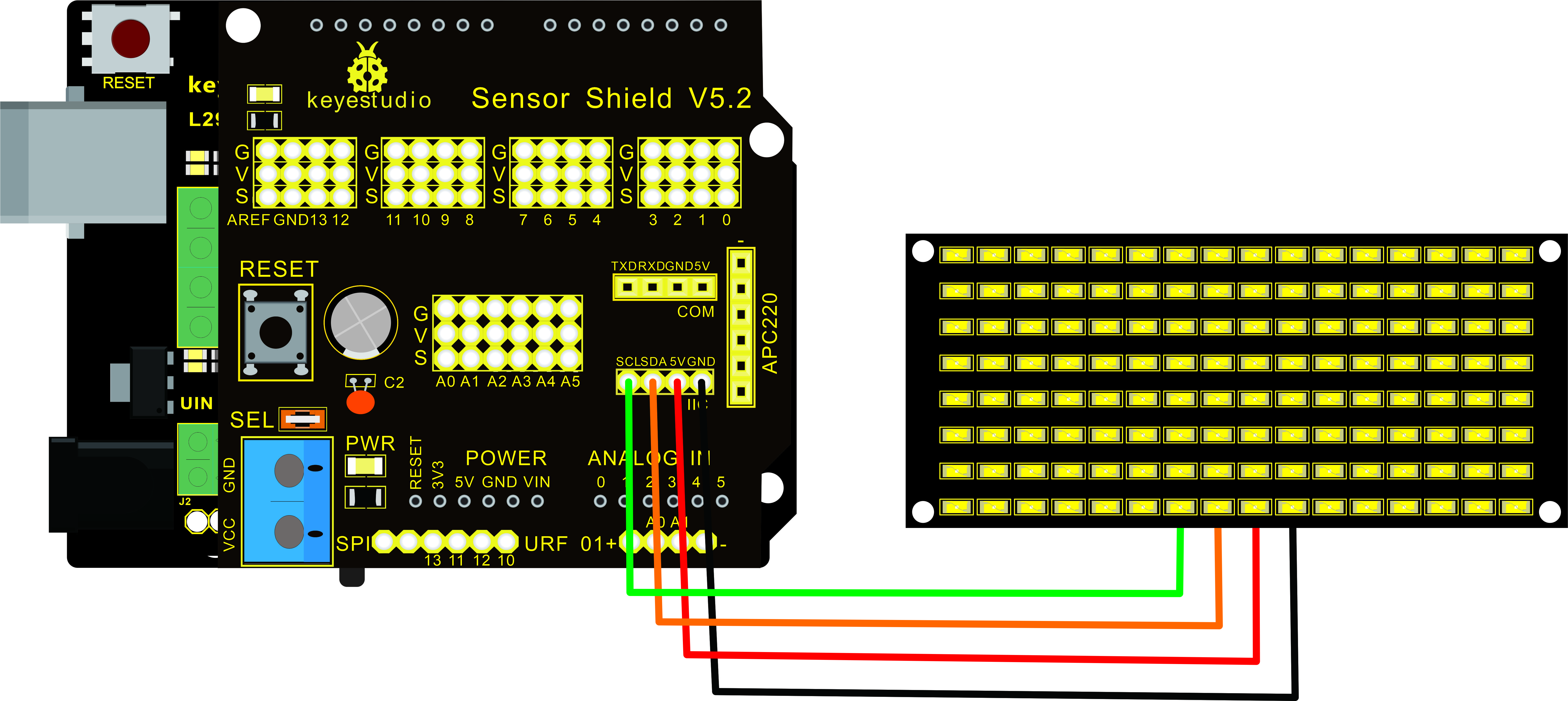
LED Panel |
V5 Sensor Shield |
|---|---|
GND |
-(GND) |
VCC |
+(VCC) |
SDA |
SDA |
SCL |
SCL |
|
|

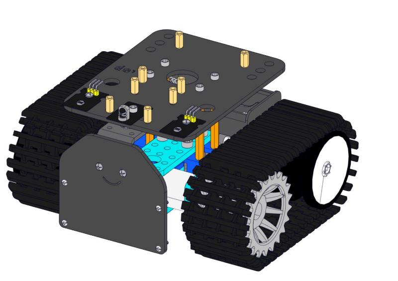
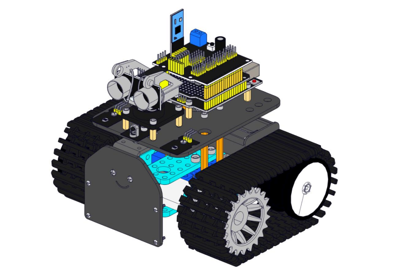
Step 9: Install all parts of Acrylic plate
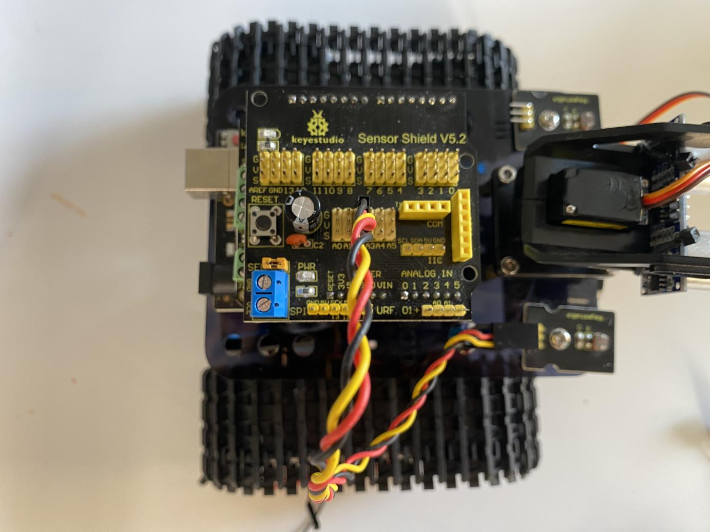
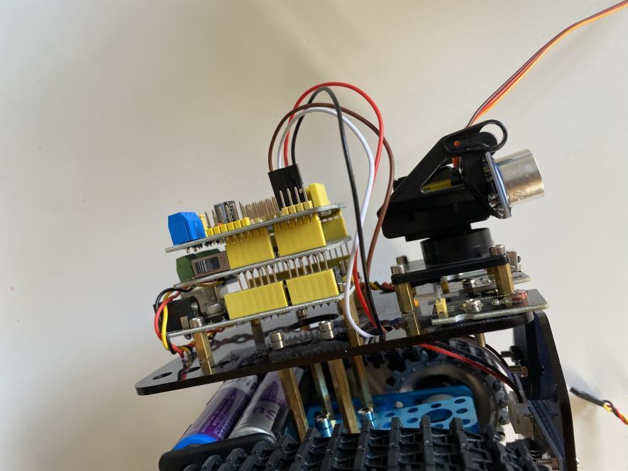
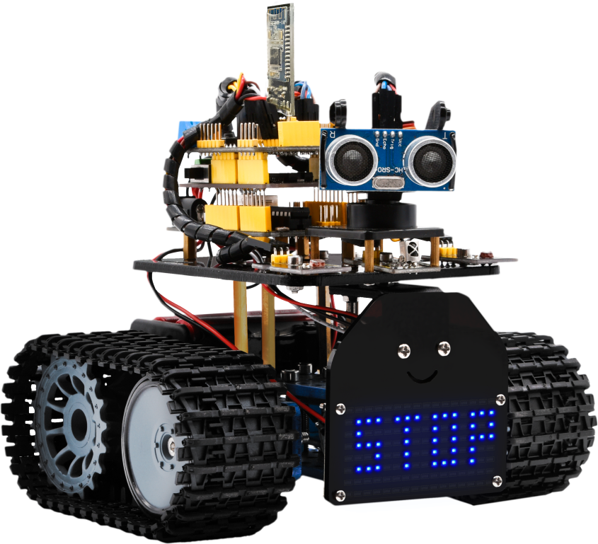
Step 10: Tank Robot
Note: Remove the Bluetooth module before uploading test code. Otherwise, you will fail to upload test code.
Multi-purpose Robot Car
Description
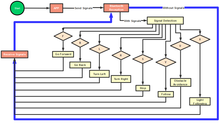
In the previous projects, the tank car only performs a single function. However, in this lesson, we integrate all of its functions to control smart car via Bluetooth control.
Here is a simple flow chart of multi-purpose robot car for your reference.
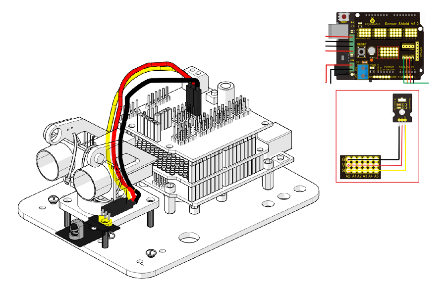
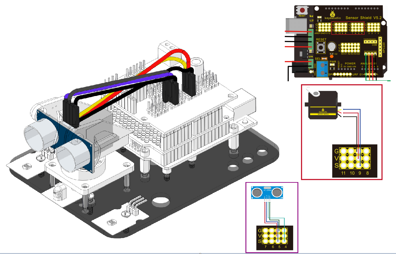
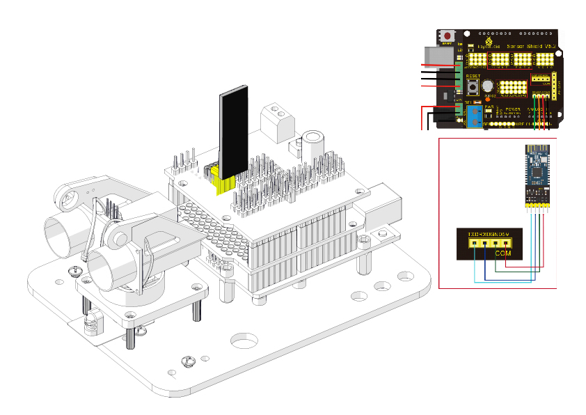
Connection Diagram
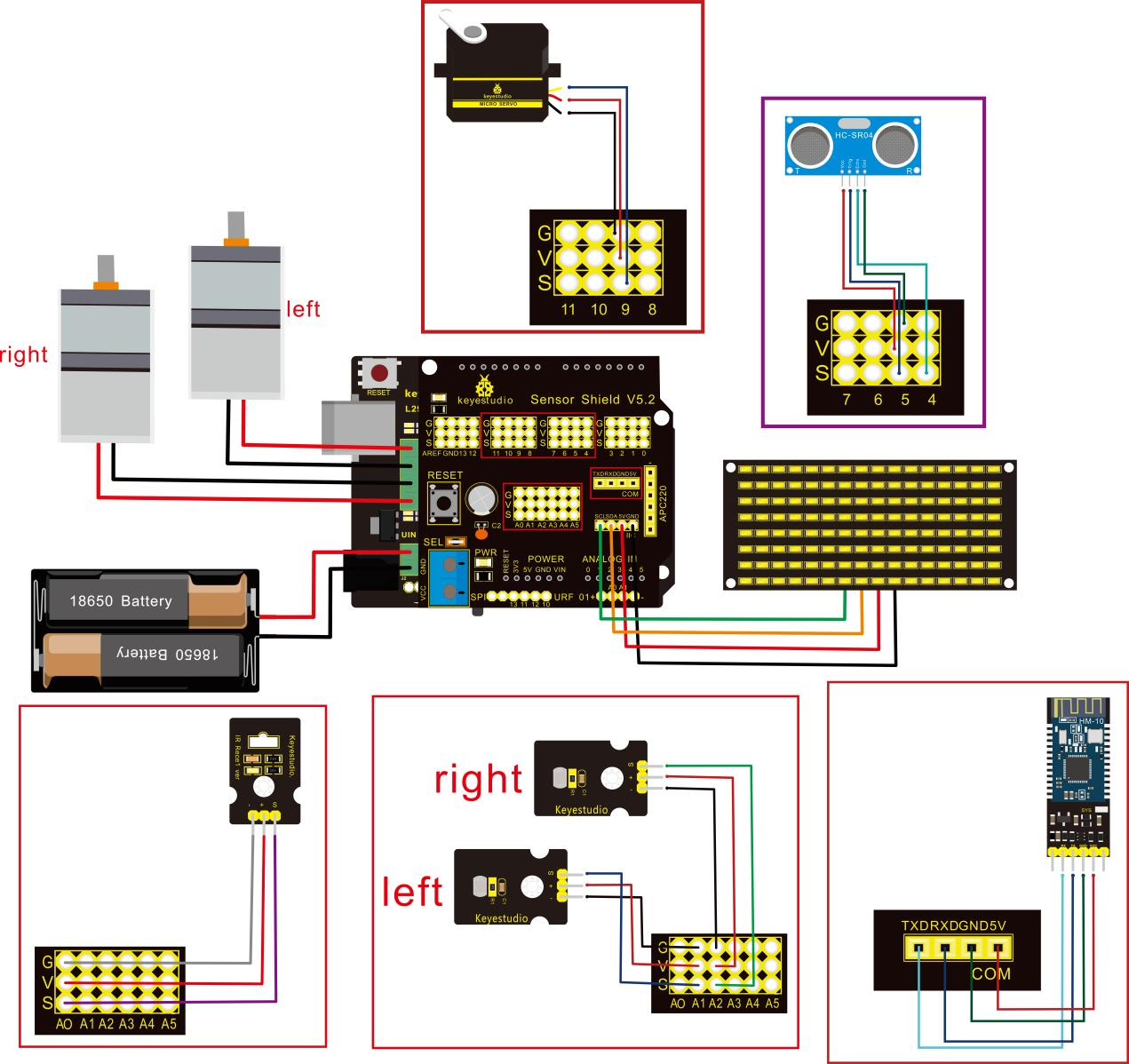
**Attention:**Confirm that every component is connected.
Wire-up Guide:
8x16 LED panel |
Expansion Board |
|
|---|---|---|
GND |
→ |
-(GND) |
VCC |
→ |
+(VCC) |
SDA |
→ |
SDA |
SCL |
→ |
SCL |
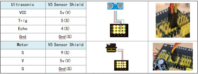
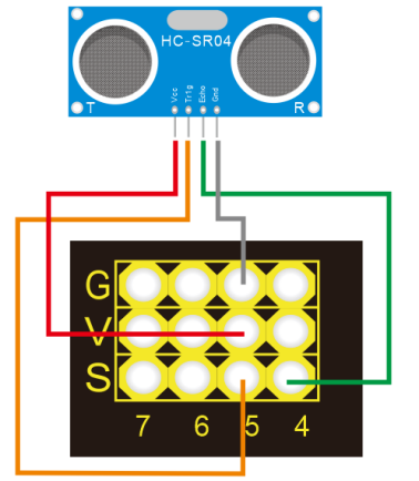
Ultrasonic Module |
||
|---|---|---|
VCC |
→ |
5v(V) |
Trig |
→ |
5(S) |
Echo |
→ |
4(S) |
Gnd |
→ |
Gnd(G) |
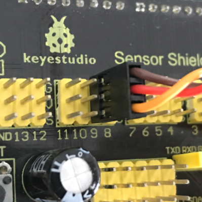
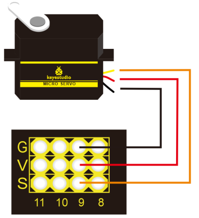
Servo Motor |
||
|---|---|---|
Servo Motor |
→ |
Gnd(G) |
Red Wire |
→ |
5v(V) |
Orange Wire |
→ |
9 |
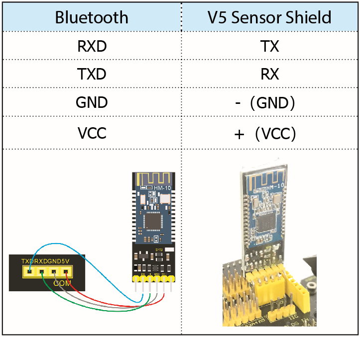
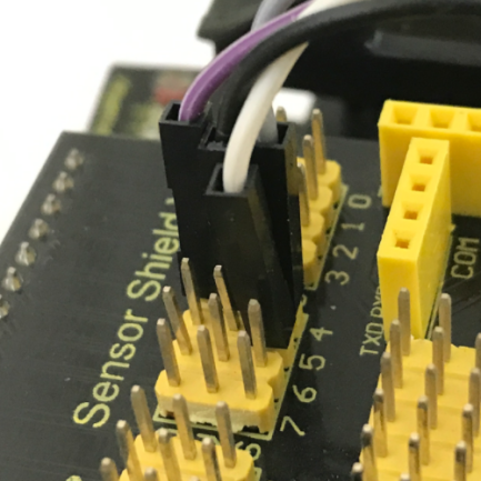
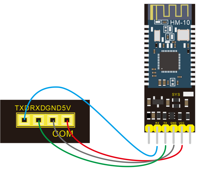
Bluetooth Module |
||
|---|---|---|
RXD |
→ |
TX |
TXD |
→ |
RX |
GND |
→ |
-(GND) |
VCC |
+(VCC) |
|
No need to attach to STATE and BRK pins |
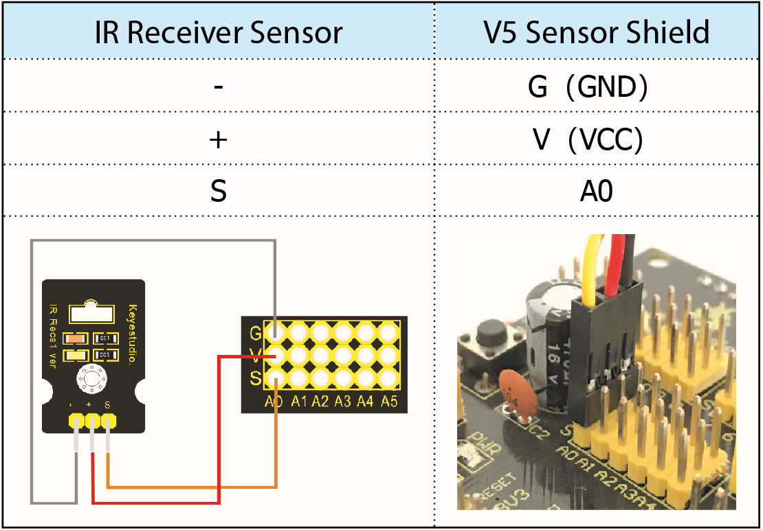
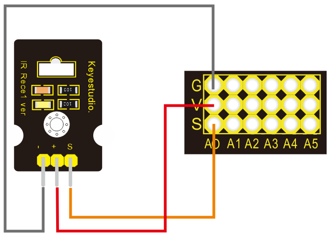
IR Receiver Module |
Sensor Shield |
|
|---|---|---|
- |
→ |
G(GND) |
+ |
→ |
V(VCC) |
S |
→ |
A0 |
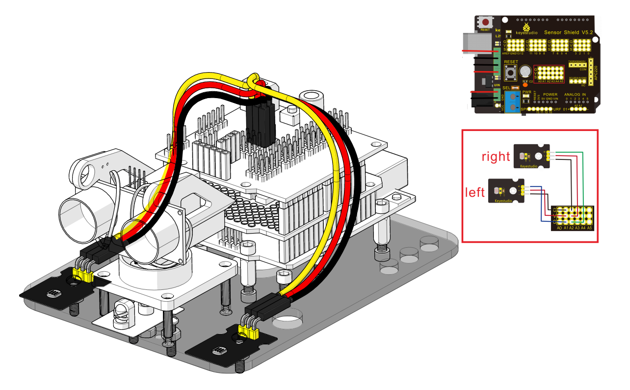
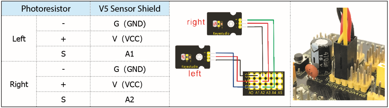
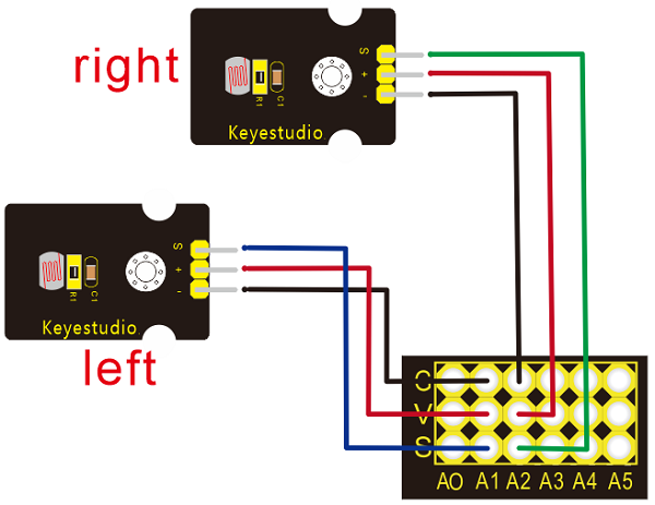
Left photo resistor |
Sensor Shield |
|
|---|---|---|
- |
→ |
G(GND) |
+ |
→ |
V(VCC) |
S |
→ |
A1 |
Right Photo resistor |
Sensor Shield |
|
- |
→ |
G(GND) |
+ |
→ |
V(VCC) |
S |
→ |
A2 |
Installation complete.