2. Product installation
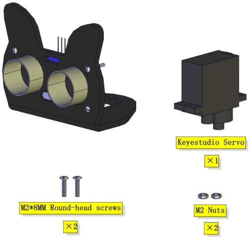
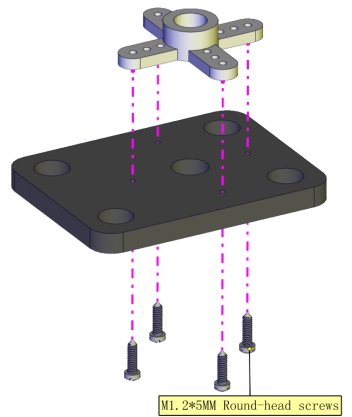
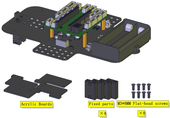
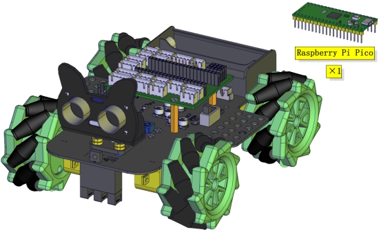
Part 1
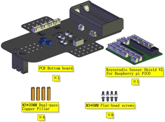
Components Needed
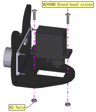
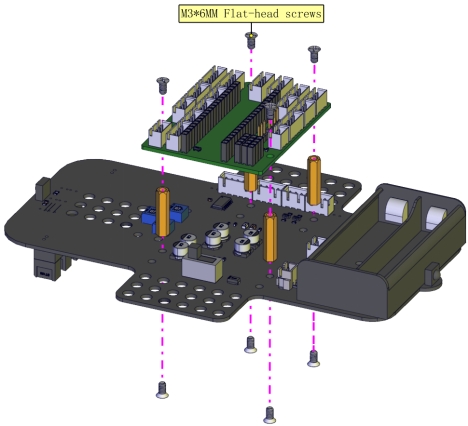
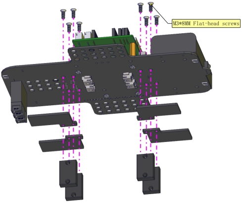
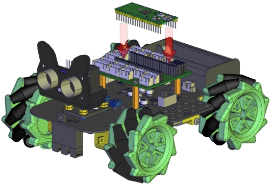
Installation Diagram
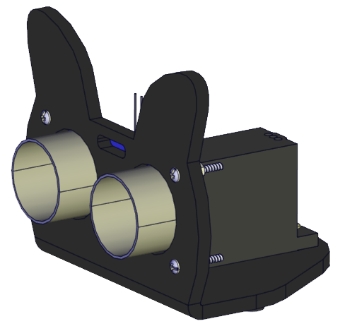
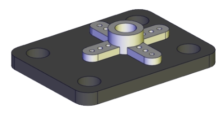
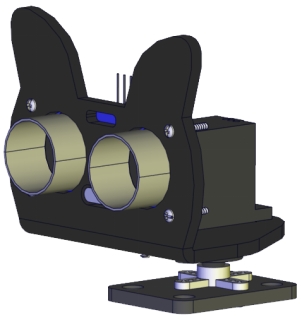
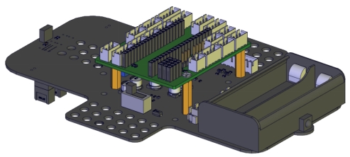
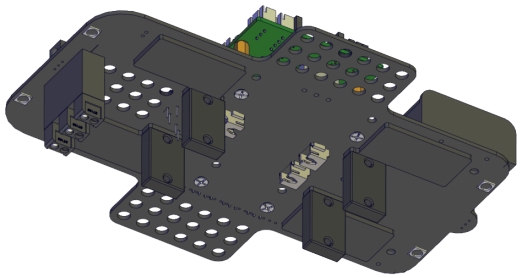
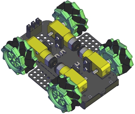
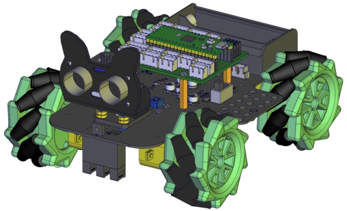
Prototype
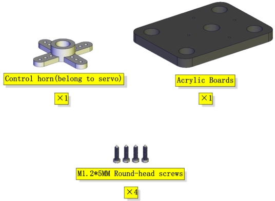
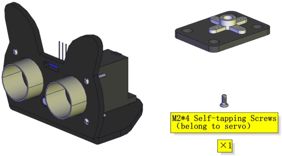
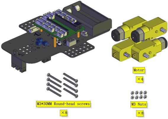
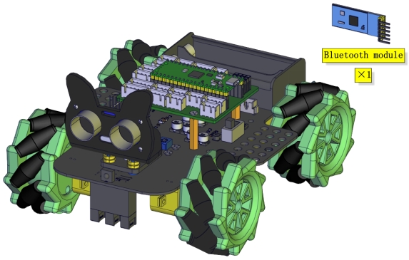
Part 2
Components Needed
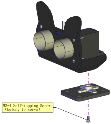
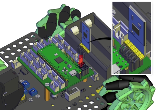
Installation Diagram
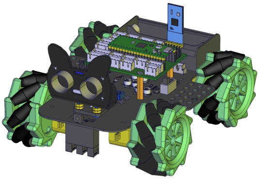
Prototype
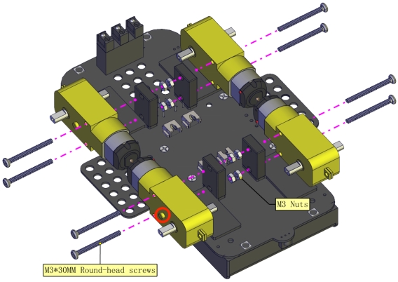
Part 3
Components Needed
Installation Diagram
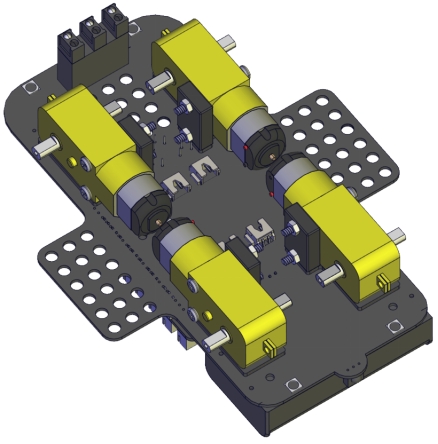
Prototype
Part 4(adjust the angle of the servo first)
Adjust the angle of the servo to 90 degrees according to the test code
#include "Servo.h"
Servo myservo;

void setup()
{
  myservo.attach(2);// attaches the servo on GIO2 to the servo object
  myservo.write(90);
  delay(500);
}

void loop()
{
}
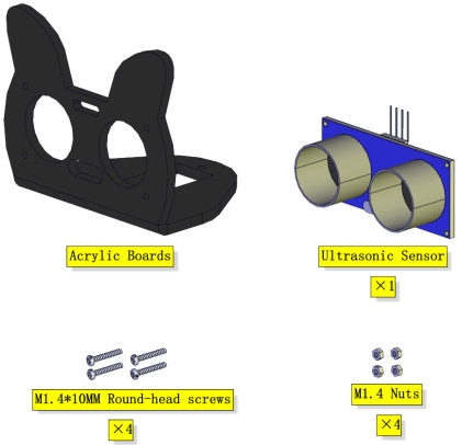
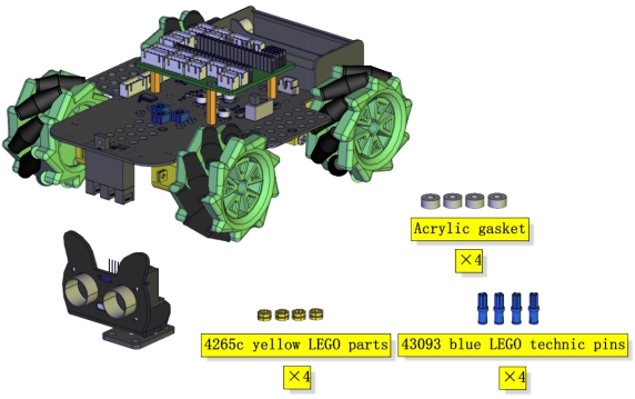
Components Needed
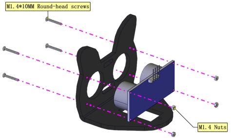
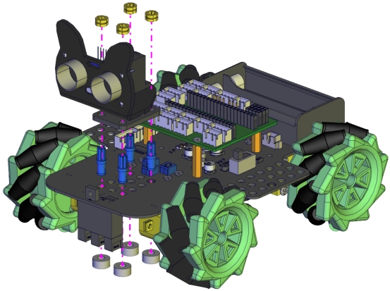
Installation Diagram(mind the installation direction)
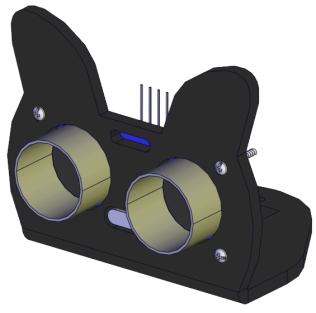
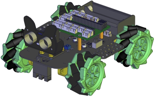
Prototype
Part 5
Components Needed
Installation Diagram
Prototype
Part 6
Components Needed
Installation Diagram
Prototype
Part 7
Components Needed
Installation Diagram(mind the direction of the motor)
Prototype
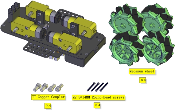
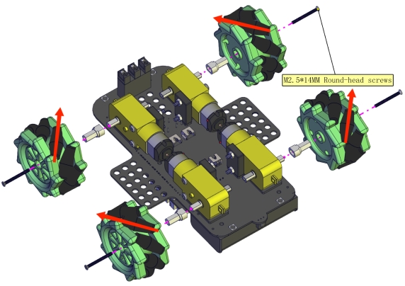
Part 8
Components Needed
Installation Diagram
(Pay attention to the installation direction of the mecanum wheel)
Prototype
Part 9
Components Needed
Installation Diagram
Prototype
Part 10
Components Needed
Installation Diagram
Prototype
Part 11
Components Needed
Installation Diagram
Prototype
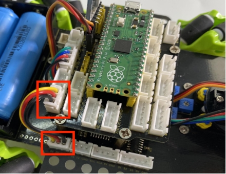
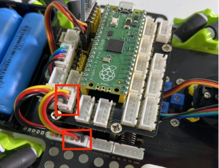
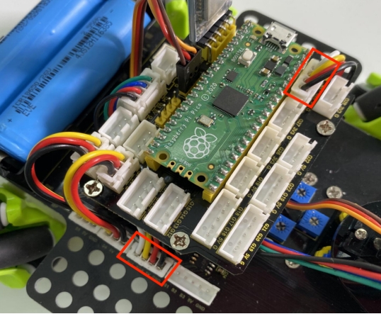
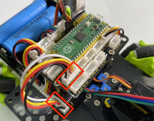
Wiring Diagram
The wiring of the servo
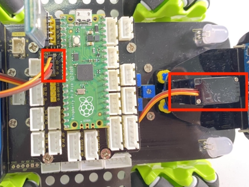
Servo |
Expansion Board |
|---|---|
Brown |
G |
Red |
5V |
Yellow |
G2 |
The wiring of the ultrasonic sensor
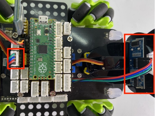
Ultrasonic Sensor |
Expansion Board |
|---|---|
VCC |
5V |
TRIG |
G3 |
ECHO |
G4 |
GND |
G |
The wiring of the IR receiver module
Driver Board |
Expansion Board |
|---|---|
GND |
G |
5V |
5V |
S5 |
G6 |
The wiring of the RGB
Driver Board |
Expansion Board |
|---|---|
GND |
G |
5V |
5V |
S4 |
G7 |
The wiring of controlling the motor and seven-color light
Driver Board |
Expansion Board |
|---|---|
SCL |
G21 |
SDA |
G20 |
5V |
5V |
GND |
G |
The wiring of controlling the 3-channel line-tracking sensor
Driver Board |
Expansion Board |
|---|---|
S1 |
G18 |
S2 |
G17 |
S3 |
G16 |
GND |
G |
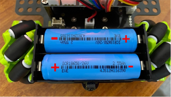
The wiring of the power supply
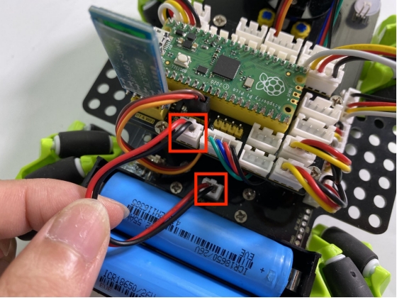
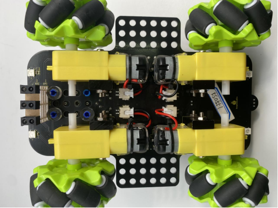
The corresponding interface of the motor
The installation of the battery