1. Product Introduction
1.1 Product Safety
1. This product contains small parts. Please keep it out of reach of children alone.
2. Please operate strictly in accordance with the tutorial to avoid product damage, and pay attention to electrical safety.
1.2 Introduction
This environment monitoring learning kit is based on Micro:bit board and integrates multiple sensors and electronic components. You can build various fun and interesting DIY projects with it to have an intuitive and vivid learning experience.
It not only enables students to experience the joy of innovation in practical operations, but also effectively cultivates their logical thinking ability, while fully demonstrating the practical and educational significance of technological applications.
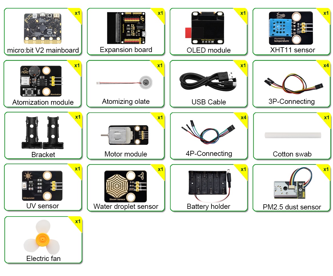
1.3 Kit List
If any components are missing, please contact our sales staff immediately.
# |
NAME |
QTY |
PIC |
|---|---|---|---|
1 |
micro:bit V2.0 main board |
1 |
|
2 |
micro:bit shield |
1 |
|
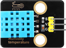
3 |
XHT11 temperature and humidity sensor |
1 |
|
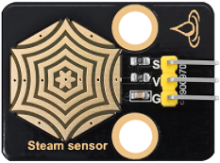
4 |
steam sensor |
1 |
|
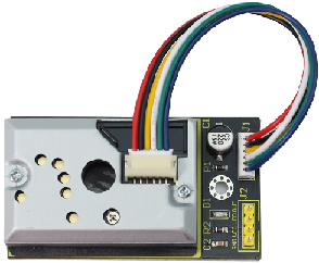
5 |
PM2.5 dust sensor |
1 |
|
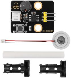
6 |
atomization module |
1 |
|
7 |
130 motor |
1 |
|
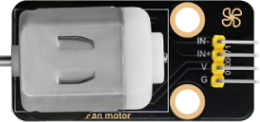
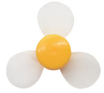
8 |
fan |
1 |
|
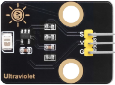
9 |
solar ultraviolet sensor |
1 |
|
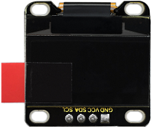
10 |
OLED module |
1 |
|
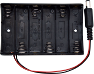
11 |
battery holder |
1 |
|
12 |
USB cable |
1 |
|
13 |
3 pin wire |
4 |
|
14 |
4 pin wire |
4 |
|
15 |
AA battery |
6 |
|
1.4 Parameters
Operating voltage: DC 3.3V ~ 5V
Battery voltage: DC 7V ~ 9V
Maximum output current: ≤1.5A
Maximum dissipation power: ≤10W
Operating temperature: -10 to +65 degrees Celsius
Product weight: 277.4g±1% (packaging included)
Packaging size: 230mm×105mm×50mm(±1%)
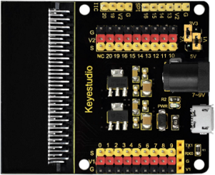
1.5 Micro:bit Shield
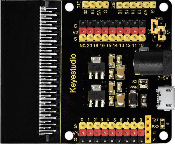
1.5.1 Introduction
In the education market, micro:bit control boards are becoming increasingly popular. However, a single micro:bit is not easy to test with other sensor modules. So we specially design this keyestudio sensor expansion board for it.
It splits all IO ports on the micro:bit board into 3-pin interfaces (GND, VCC, Signal), making it very convenient to connect the board and other sensor modules.
In addition, it also extends some commonly used serial communication interfaces to pins or female headers with a spacing of 2.54mm, including I2C and SPI communication pins. Therefore, it enables communication between the micro:bit and other communication devices.
The micro:bit can be powered through the black DC port(DC 7-9V) or the micro USB port(DC 5V) on the expansion board.
When powering the sensor, the supply voltage can be selected as 3.3V or 5V by the jumper caps V1 and V2.
⚠️ Attention:
When external sensors are connected to the board, the working current of the AMS1117-3.3V and NCP1117ST50T3G chips will be very large, causing overheating. Please avoid direct contact with these chips to prevent burns.
1.5.2 Parameters
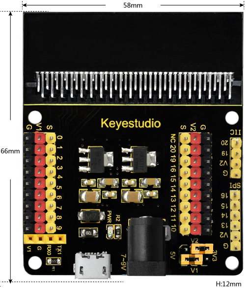
Input voltage: Black DC port (DC 7-9V) or micro USB port (DC 5V)
Output voltage: 3.3V/5V via jumper caps V1/V2
A power indicator
Splits the IO ports of the micro:bit board into 3-pin interfaces
Serial communication pin
I2C communication pin
SPI communication pin
Dimensions: 66mm x 58mm x 12mm
Weight: 31 g
1.5.3 Pin-out

PIC |
V1 voltage/V |
V2 voltage/V |
|---|---|---|
|
3.3 |
3.3 |
|
3.3 |
5 |
|
5 |
5 |
|
5 |
3.3 |


1.6 About Micro:bit
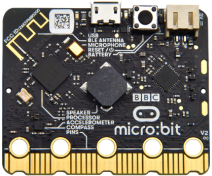
1.6.1 What is Micro:bit?
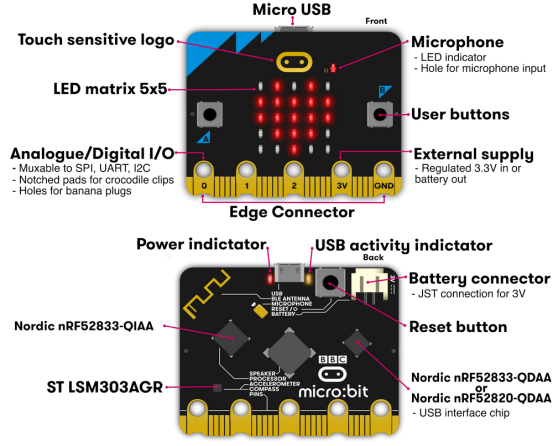
Micro:bit is a microcomputer development board used for programming education among teenagers, which is launched by the British Broadcasting Corporation (BBC).
Though it is just the size of a credit card, the Micro:bit V2.0 board is equipped with loads of components, including a 5×5 LED dot matrix, 2 programmable buttons, an accelerometer, a compass, a thermometer, a touch-sensitive logo and a MEMS microphone, a Bluetooth module of low energy, and a buzzer and others. Thus, it also boasts multiple functions. The buzzer built in the other side of the board plays all kinds of sounds without any external equipment. Moreover, this board has a sleeping mode to lower power consumption of batteries when users long-press the Reset & Power button on the back.
1.6.2 Micro:bit V2 Board
1.6.3 Micro:bit V2 Pin-out
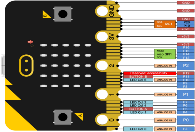
The functions of the micro:bit pins are shown in the following table:
Function |
Pin |
|---|---|
GPIO |
P0,P1,P2,P3,P4,P5,P6,P7,P8,P9,P10,P11,P12,P13,P14,P15,P16,P19,P20 |
ADC/DAC |
P0,P1,P2,P3,P4,P10 |
IIC |
P19(SCL),P20(SDA) |
SPI |
P13(SCK),P14(MISO),P15(MOSI) |
PWM |
P0,P1,P2,P3,P4,P10 |
Occupied |
P5(Button A),P6(LED Col4),P7(LED Col2),P10(LED Col5),P11(Button B) |
For detailed information, please refer to these official websites:
1.6.4 Notes for Application
1. It is recommended to cover it with a silicone protector to prevent short circuits, as it has many sophisticated electronic components.
2. Its IO port has limited drive capability and can handle a current of less than 300mA. Therefore, do not connect it with high-current devices such as the MG995 servo or DC motor, or it may get burnt. Furthermore, always check the current requirements of connected devices beforehand, and it is generally recommended to use the board together with a Micro:bit shield.
3. It is recommended to power the main board via the USB interface or via the battery of 3V. The IO port of this board is 3V3, so it does not support sensors of 5V. If you need to connect sensors of 5V, a micro:bit shield is required.
4. When using pins (P3, P4, P6, P7 and P10) shared with the LED dot matrix, you must disable the LED matrix first; otherwise the LEDs may display randomly and sensor readings may be incorrect.
5. Pin 19 and 20 can not be used as IO ports though the Makecode shows they can. They can only be used as I2C communication.
6. The battery port of 3V cannot be connected with battery more than 3.3V or the main board will be damaged.
7. Forbid to operate it on metal products to avoid short circuit.
To put it simply, the micro:bit board is like a microcomputer that has made programming accessible to everyone and enhanced digital innovation.