4.4Line Detection
4.4.1 Algorithm
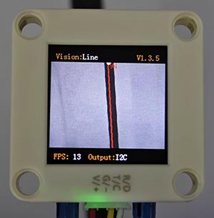
It will determine whether there are line segments in the image. If there are, it will return the coordinates of the two endpoints of the line segment and the inclination angle. If the line is a curve, it will return the inclination angle of the straight line formed by the connection of the starting and the ending point of the curve.
4.4.2 Code Blocks
 sets the number of lines to be detected, with a minimum of 1 and a maximum of 5.
Note: The first line on the display is red, the second is yellow, the third is green, the fourth is blue, and the fifth is purple.
 returns the data of lines.
Parameter |
Definition |
|---|---|
x-coord of ending point |
x-coordinate of the end point (distal end) of the line segment |
y-coord of ending point |
y-coordinate of the end point (distal end) of the line segment |
x-coord of starting point |
x-coordinate of the starting point (proximal end) of the line segment |
y-coord of starting point |
y-coordinate of the starting point (proximal end) of the line segment |
inclination angle |
inclination angle of the line segment |
Note: The inclination angle increases counterclockwise. When it is horizontally tilted to the right, the angle is 0°; when it is vertically tilted upwards, it is 90°; and when it is horizontally tilted to the left, it is 180°. The algorithm does not detect the angle downward.
4.4.3 Tips of Line Detection Algorithm
Do not use glossy maps to avoid reflect light which may lead to detection failure.
The line boundaries should be clear and with obvious color differences from background, such as a white background with black lines;
The background should be as simple as possible, for example, containing a single color. If it is messy, lines of the background may be detected.
The thickness of the lines should be moderate. Both being too thin and too wide will affect the detection.
When traversing, the first line segment is always the one first detected at the bottom of the screen.
4.4.4 Test Code
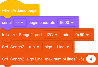
In the code start-up, set the serial port baud rate to
9600, and then set the communication mode of the AI vision module toI2C, and finally set it to run inLinemode.Set the number of recognition lines. We set it to 4
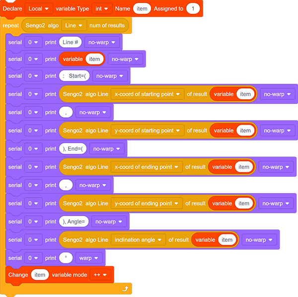
The if block determines the number of detections. Only when the number of detections is greater than 0 will the data be output. Note to choose
Line.Loop through the result quantity. When multiple lines are detected, it will loop multiple times and then use a variable on the parameter group. After each loop print, the variable adds by one. In this way, the data of lines can be printed (Note: Set the mode of the returned data to “Line”).
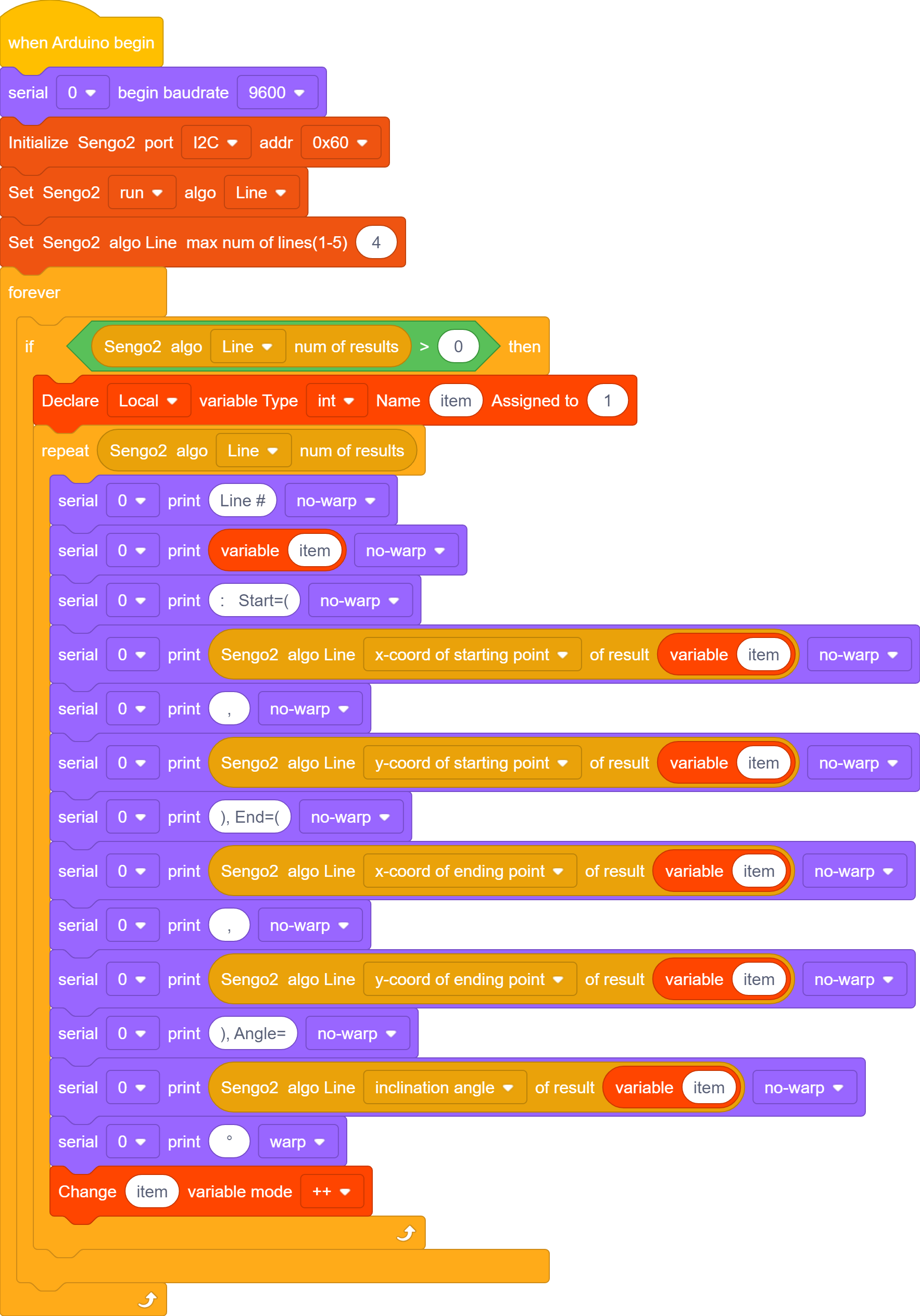
Complete code:
4.4.5 Test Result
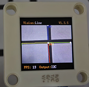
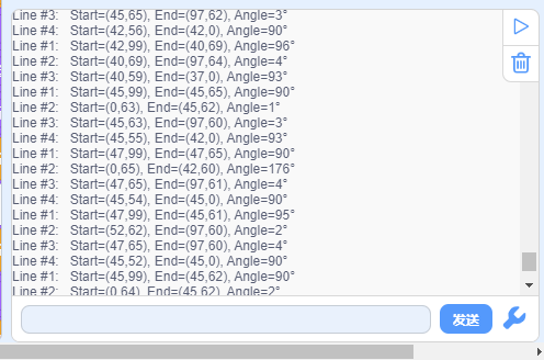
After uploading the code, the module will detect the area captured by the camera. If there are lines, they will be recognized and the starting and ending coordinates of lines as well as their angles will be printed in the serial monitor (the angle determination is 90 degrees for vertical lines and 180 degrees for horizontal lines).
4.4.6 Extension Gameplay
Distinguish triangles and rectangles
Game rule: Print triangles and rectangles onto an A4 paper with thick lines. Then, enable line detection function to detect them. If three lines are detected, it is a triangle; if four lines are detected, it is a rectangle.
Practice: The development board reads and counts the number of recognized lines. If the number of lines is 3, it is a triangle; if it is 4, it is a rectangle.