2. Product installation
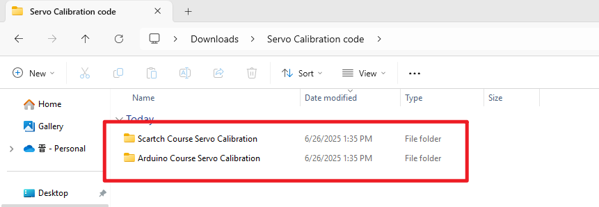
Servo Calibration Code Download:Servo Calibration code
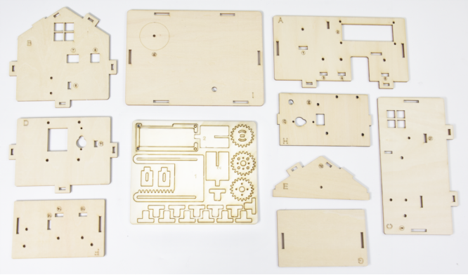
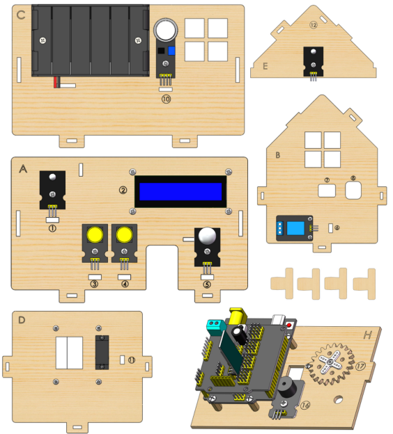
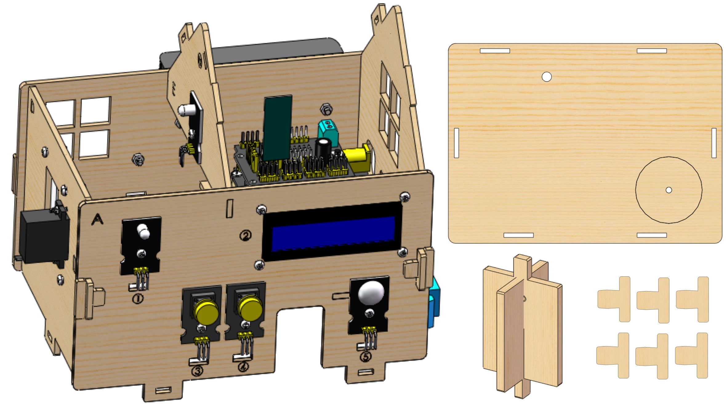
Check board A~I and other parts
Step 1
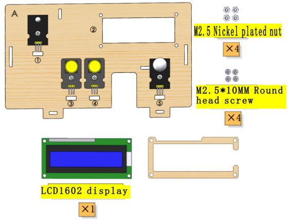
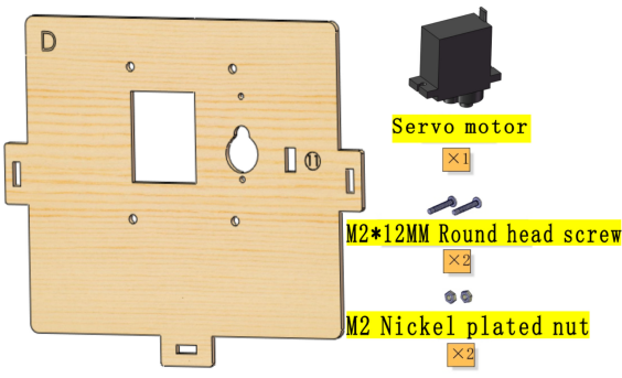
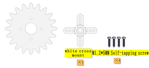
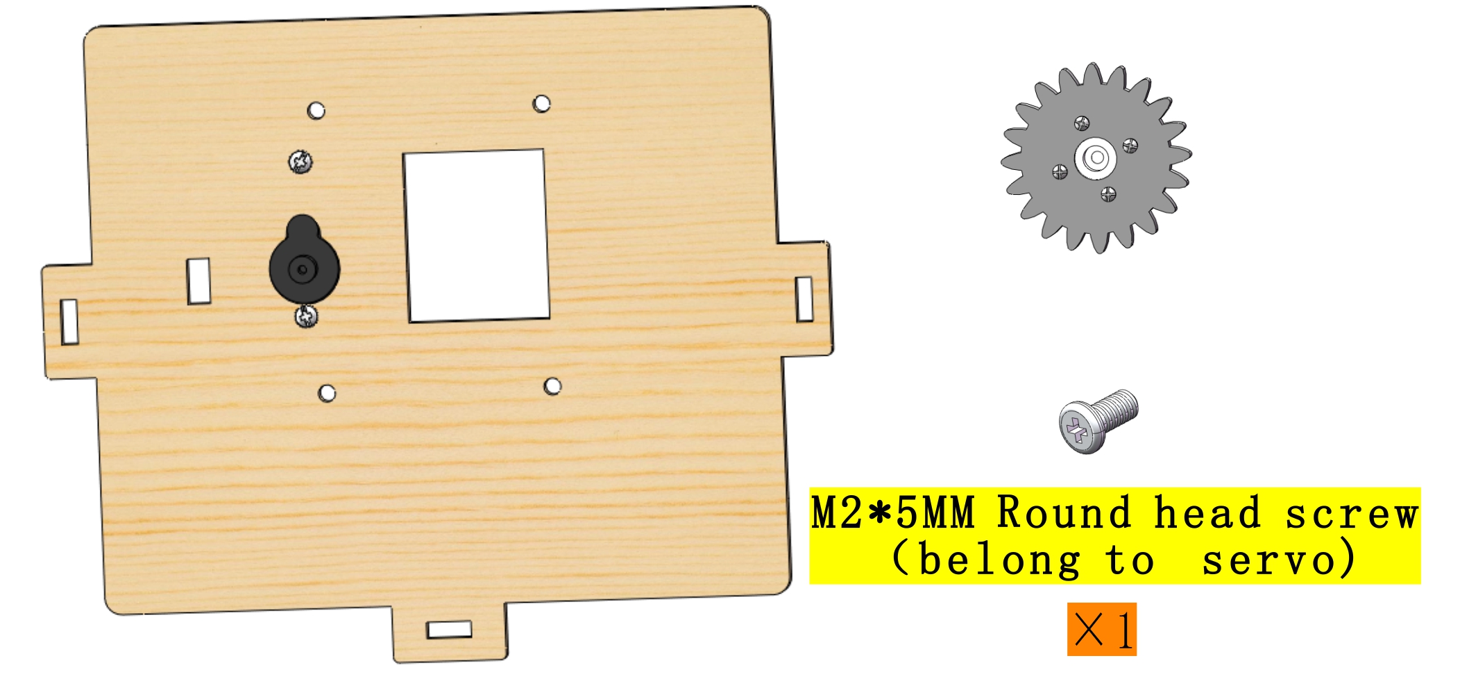
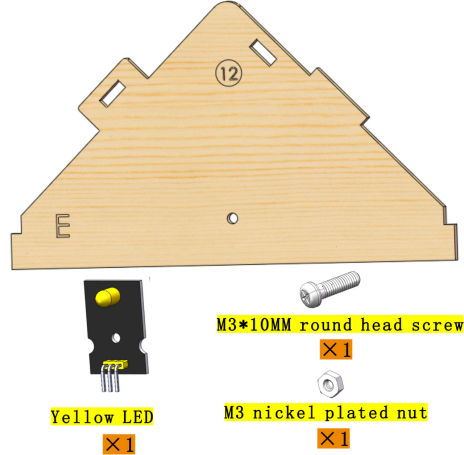
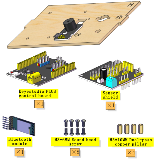
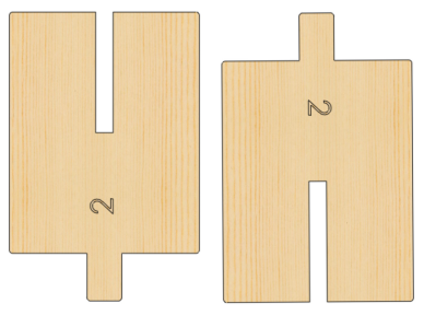
Needed Components:
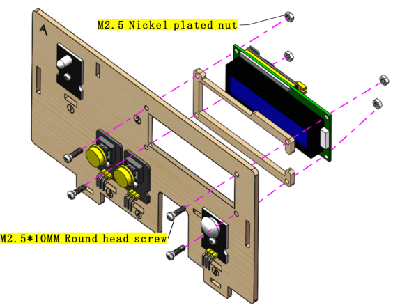
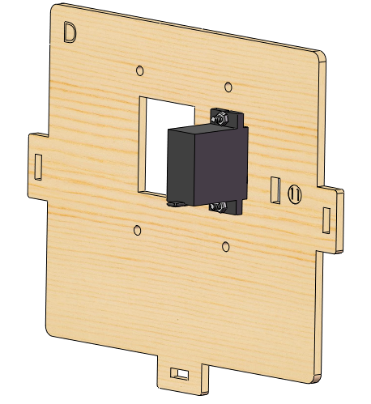
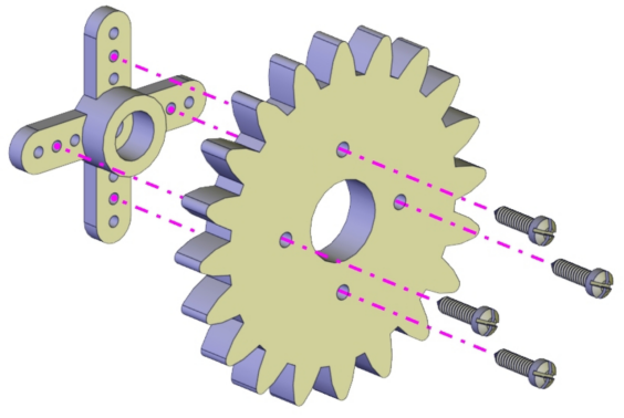
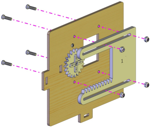
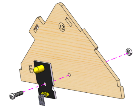
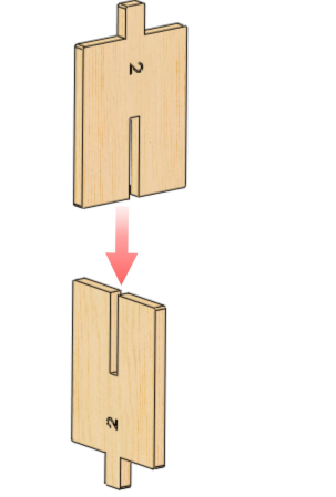
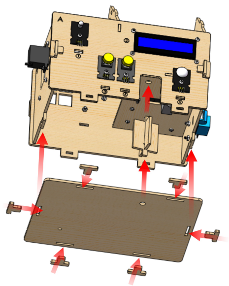
 Installation Diagram:
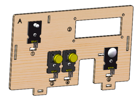
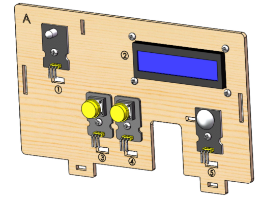
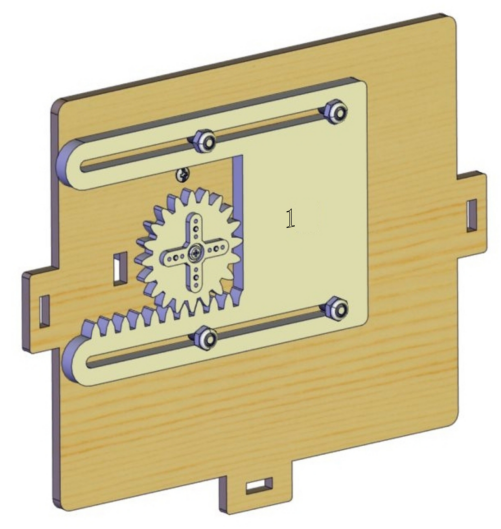
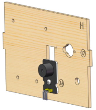
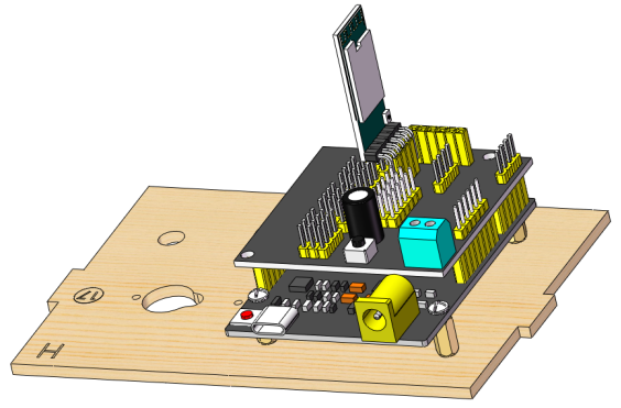
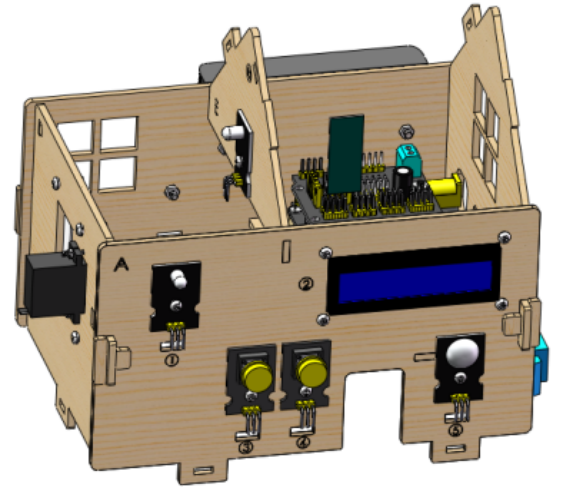
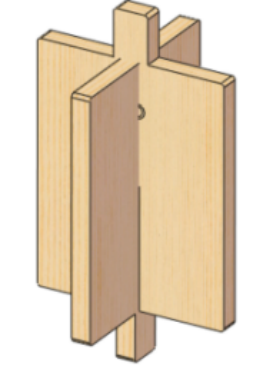
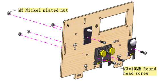 Prototype:
Step 2
Needed Components:
 Installation Diagram:
 Prototype:
Step 3
Needed Components:
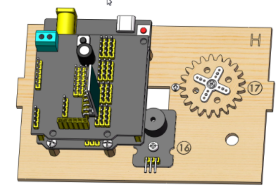
 Installation Diagram:
 Prototype:
Step 4
Needed Components:
 Installation Diagram:
 Prototype:

Step 5
Needed Components:
 Installation Diagram:
 Prototype:
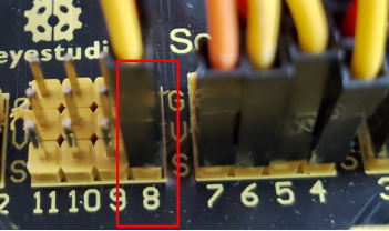
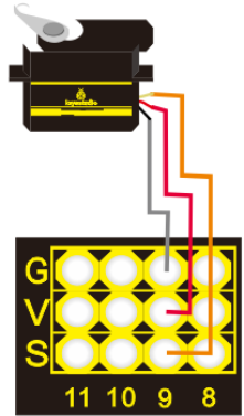
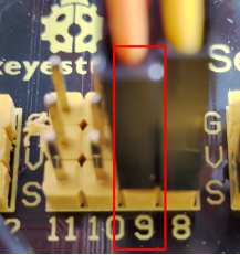
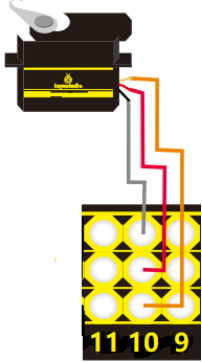
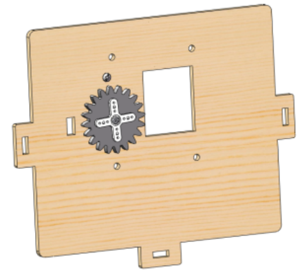 Set the angle of the Servo which controls the window to 90°:
Servo for window |
PLUS Mainboard |
|---|---|
Brown line |
G |
Red line |
V |
Orange line |
S(10) |
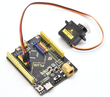
Wire up as shown in the picture and upload the code to the expansion board. Install the Servo after it automatically turn to 90°。
Servo calibration requires uploading code, please refer to the corresponding course (Arduino or Scartch) to install the programming software and upload the servo code of the course you are using.
(Note: This step is necessary.)
Step 6
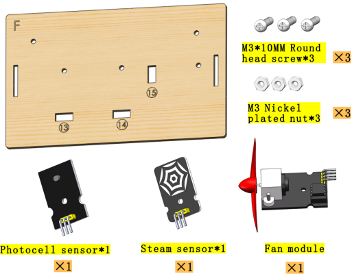
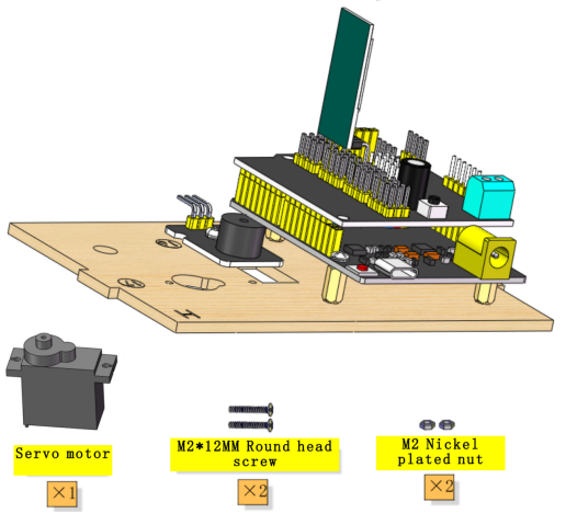
Needed Components:
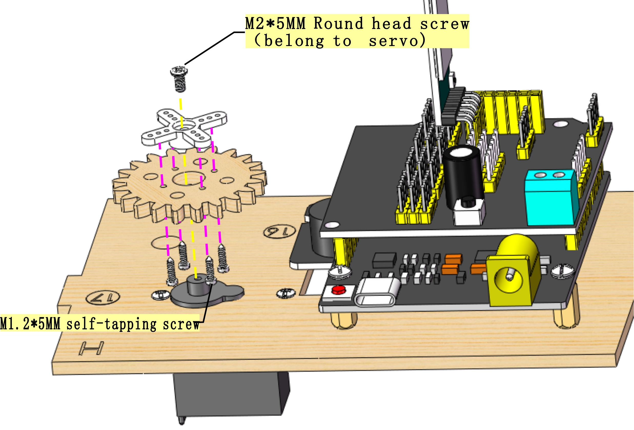
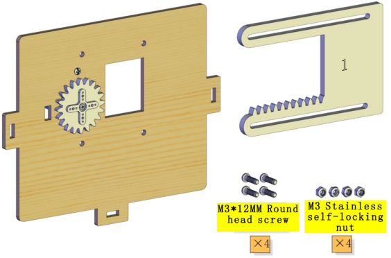 Installation Diagram:
(Please do not tighten the self-locking nut when installing it. The window is closed during installation as shown below:)
Installation Diagram:
(Please do not tighten the self-locking nut when installing it. The window is closed during installation as shown below:)
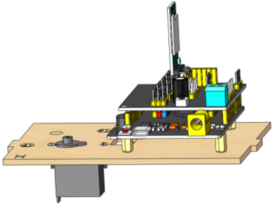
 Prototype:
Step 7
Needed Components:
 Installation Diagram:
 Prototype:
Step 8
Needed Components:
 Installation Diagram:
 Prototype:
Step 9
Needed Components:
 Installation Diagram:
 Prototype:
Step 10
Needed Components:
 Installation Diagram:
 Prototype:

Step 11
Needed Components:
 Installation Diagram:
 Prototype:
Step 12
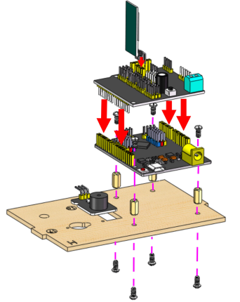
Needed Components:
 Installation Diagram:
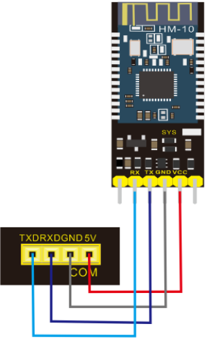
Bluetooth module |
Expansion board |
|---|---|
VCC |
5V |
GND |
GND |
TXD |
RXD |
RXD |
TXD |
Prototype: |
Prototype:
Step 13
Needed Components:
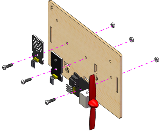
 Installation Diagram:
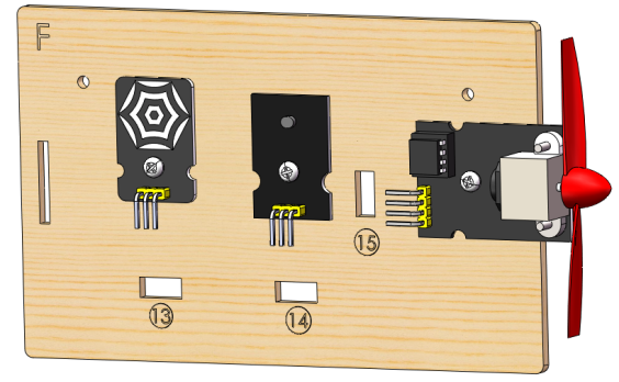
 Prototype:
Step 14
Needed Components:
 Installation Diagram:
 Prototype:
Step 15
Needed Components:
 Installation Diagram:
 Prototype:
Step 16
Needed Components:
 Installation Diagram:
 Prototype:
Step 17
Needed Components:
 Installation Diagram:
 Prototype:
Step 18
Needed Components:
 Installation Diagram:
 Prototype:
Step 19
Needed Components:
 Installation Diagram:
 Prototype:

Wiring
PIR Motion Sensor
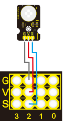
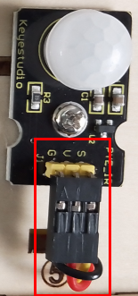
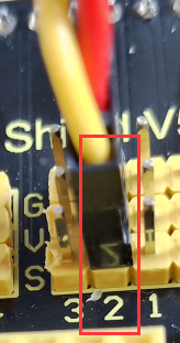
PIR motion sensor |
Expansion board |
Position on wood board |
|---|---|---|
G/V/S |
G/V/2 |
⑤ |
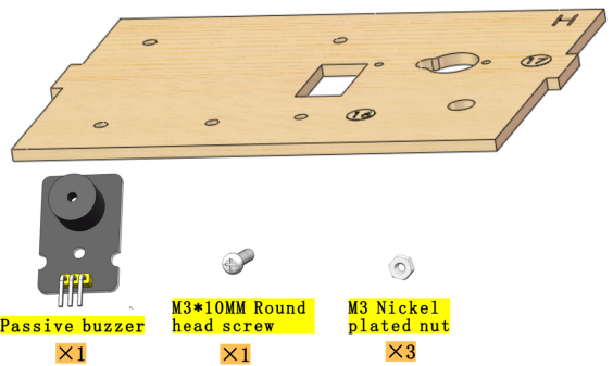
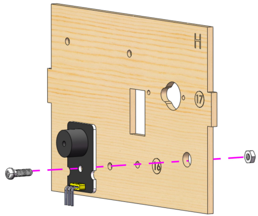
Passive Buzzer
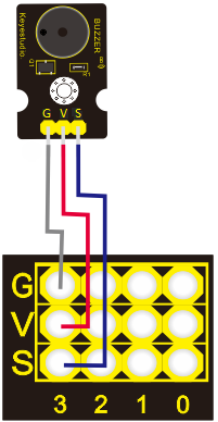
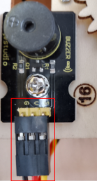
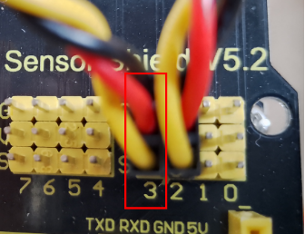
Passive buzzer |
Expansion board |
Position on wood board |
|---|---|---|
G/V/S |
G/V/3 |
⑯ |
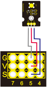
Button 1
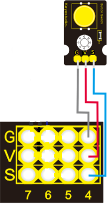
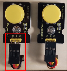
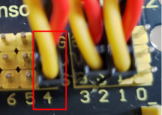
Button 1 |
Expansion board |
Position on wood board |
|---|---|---|
G/V/S |
G/V/4 |
③ |
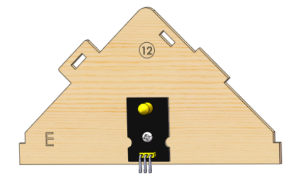
Yellow LED
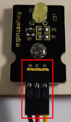
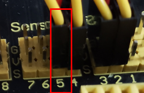
Yellow LED |
Expansion board |
Position on wood board |
|---|---|---|
G/V/S |
G/V/5 |
⑫ |
Fan

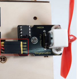
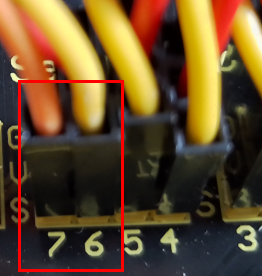
Fan |
Expansion board |
Position on wood board |
|---|---|---|
GND/VCC/INA/INB |
G/V/7/6 |
⑮ |
Button 2
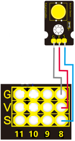

Button 2 |
Expansion board |
Position on wood board |
|---|---|---|
G/V/S |
G/V/8 |
④ |
Servo 1 for Door Controlling
Servo 1 |
Expansion board |
Position on wood board |
|---|---|---|
Brown line/Red line/Orange line |
G/V/9 |
⑰ |
Servo 2 for Window Controlling
Servo 2 |
Expansion board |
Position on wood board |
|---|---|---|
Brown line/Red line/Orange line |
G/V/10 |
⑪ |
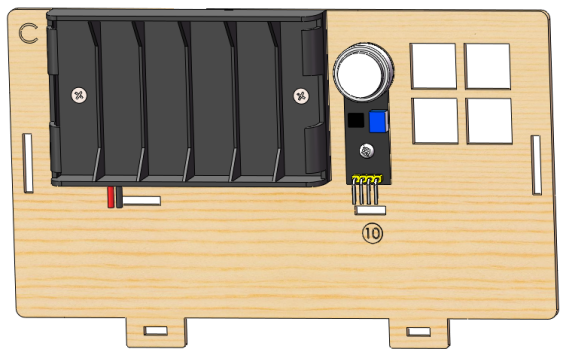
MQ-2 Gas Sensor
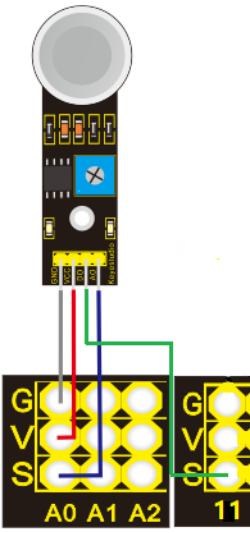
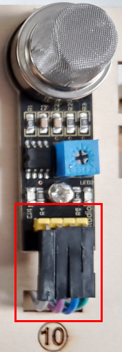
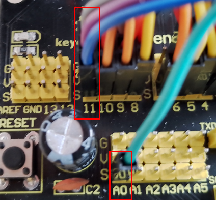
MQ-2 gas sensor |
Expansion board |
Position on wood board |
|---|---|---|
GND/VCC/D0/A0 |
G/V/11/A0 |
⑩ |
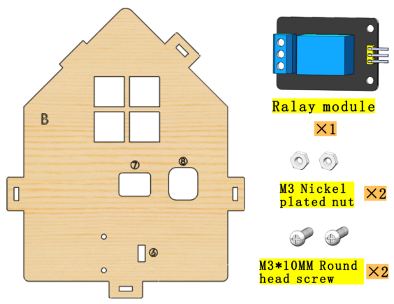
Relay Module
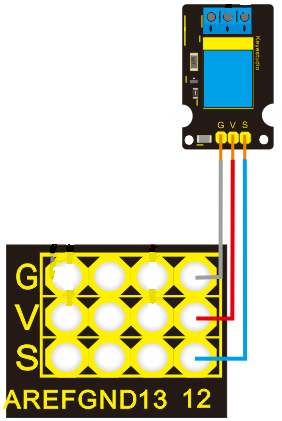
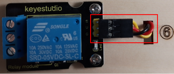
Relay module |
Expansion board |
Position on wood board |
|---|---|---|
G/V/S |
G/V/12 |
⑥ |
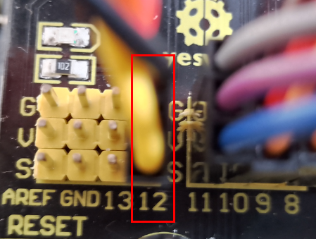
White LED
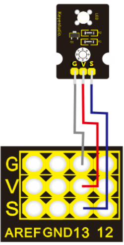
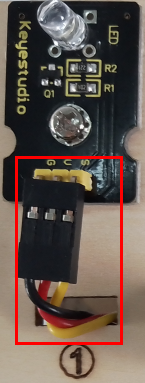
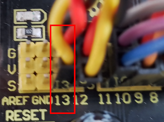
White LED |
Expansion board |
Position on wood board |
|---|---|---|
G/V/S |
G/V/13 |
① |
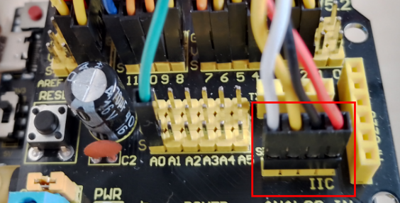
LCD1602 Display
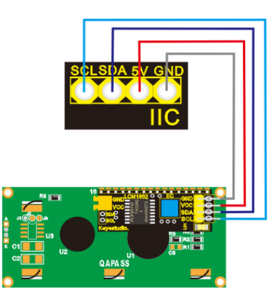
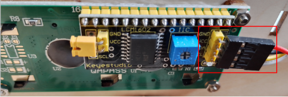
LCD1602 display |
Expansion board |
Position on wood board |
|---|---|---|
GND/VCC/SDA/SCL |
GND/5V/SDA/SCL |
② |
Photocell Sensor
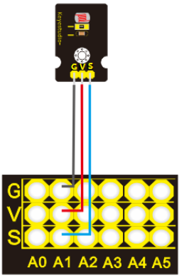
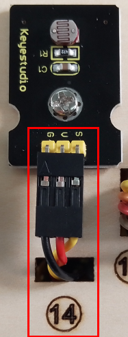
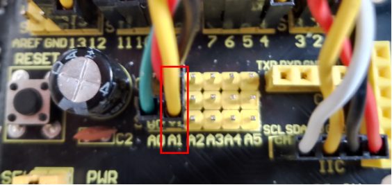
photocell sensor |
Expansion board |
Position on wood board |
|---|---|---|
G/V/S |
G/V/A1 |
⑭ |
Soil Humidity Sensor
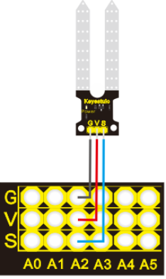
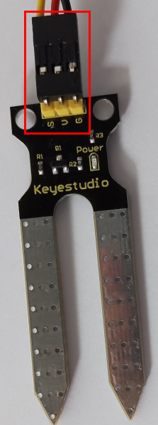
soil humidity sensor |
Expansion board |
Position on wood board |
|---|---|---|
G/V/S |
G/V/A2 |
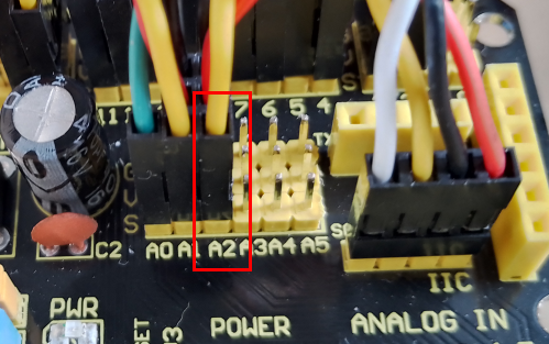
Steam Sensor
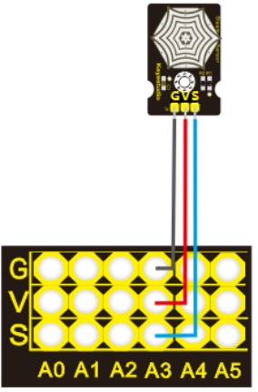
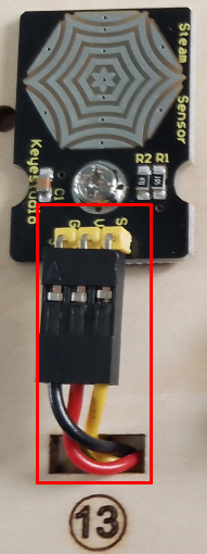
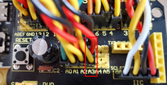
steam sensor |
Expansion board |
Position on wood board |
|---|---|---|
G/V/S |
G/V/A3 |
⑬ |
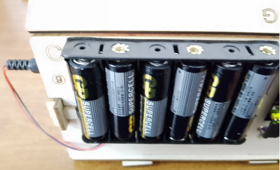
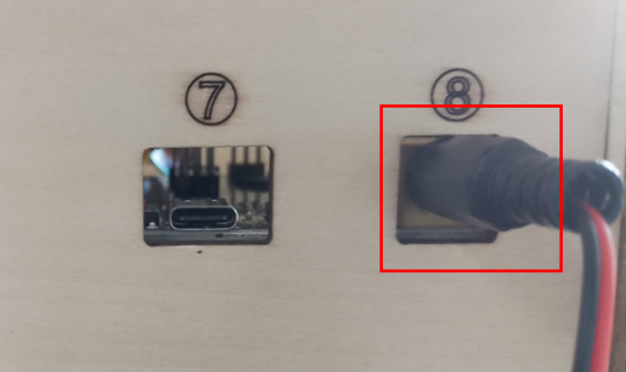
Power Supply
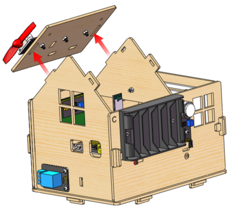
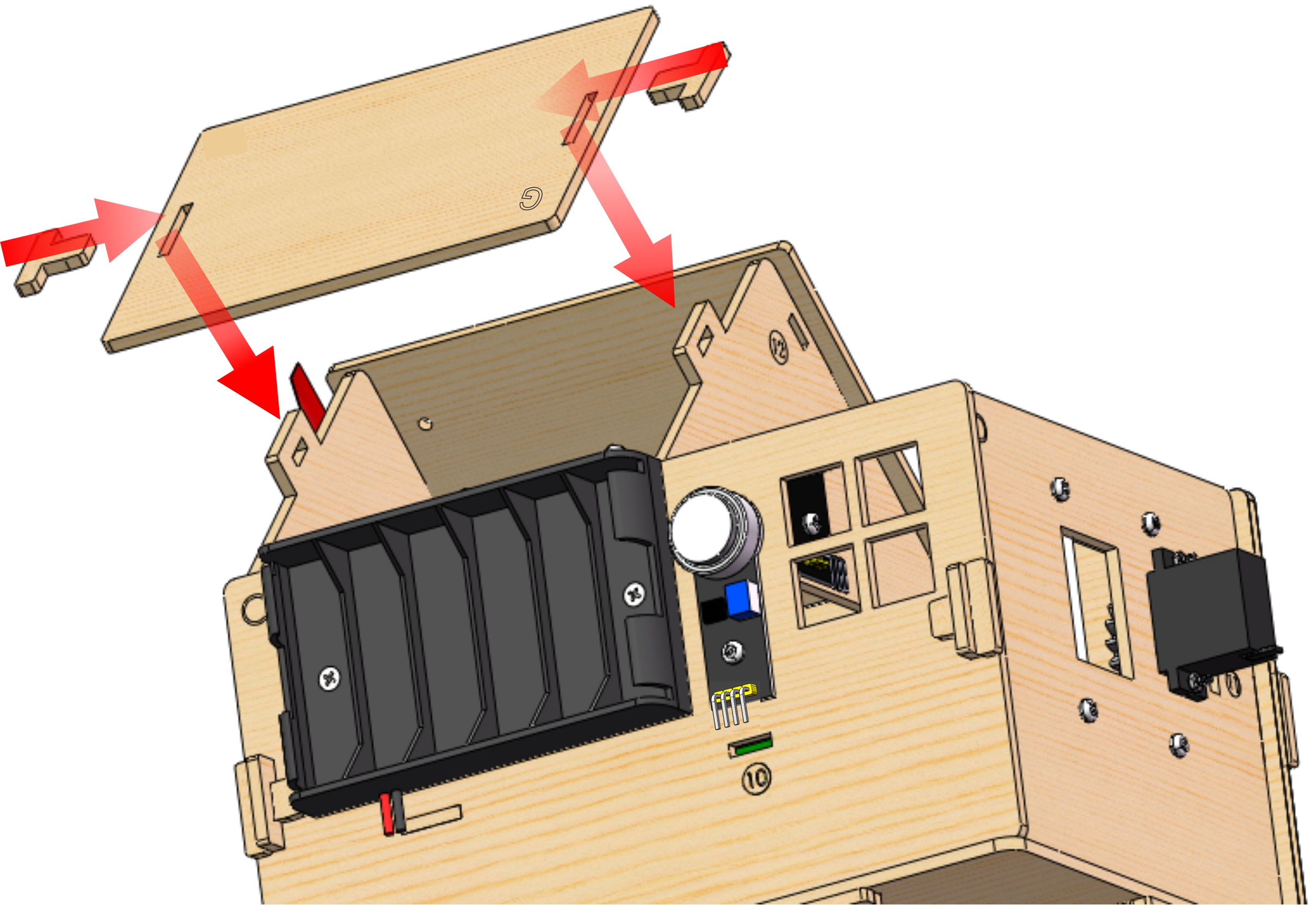
Last Step: Roof Installation
Needed Components
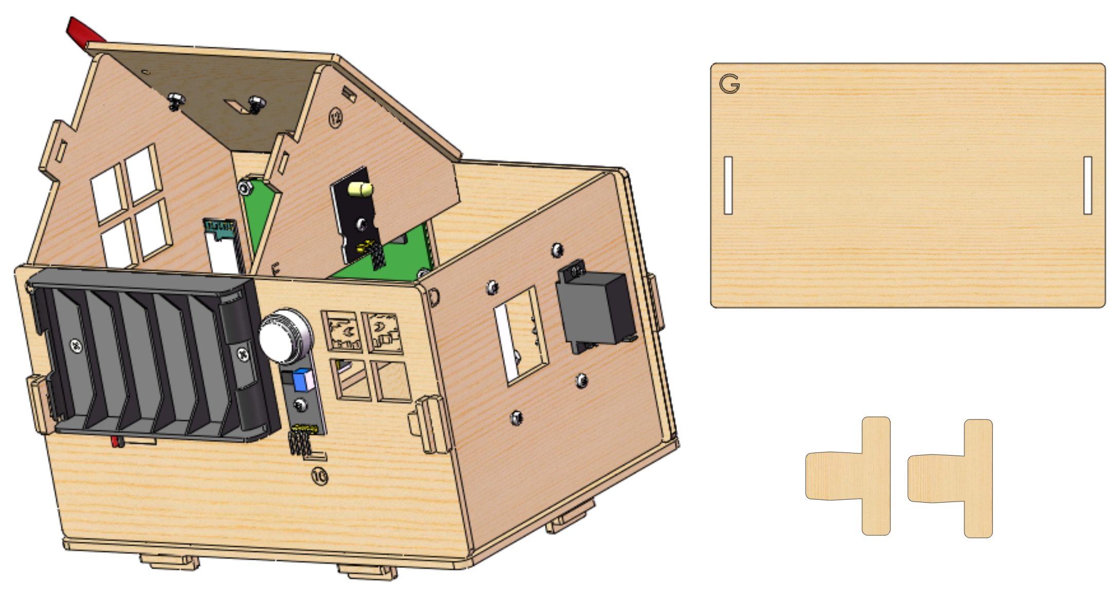 Installation Diagram
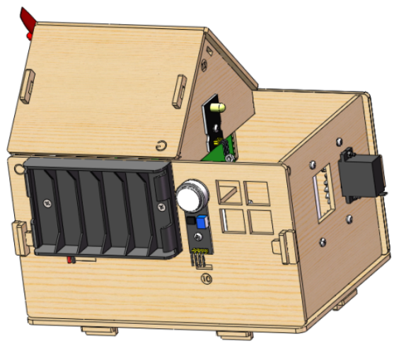
 Prototype