Project 10 IR Remote Control
1.Description
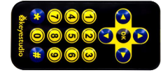
There is no doubt that the IR remote control can be seen everywhere in our daily life, which is used to control a broad menu of appliances, including TVS, stereos, VCRS and satellite receivers.
It is composed of an infrared remote control and an infrared receiver module as well as a single chip microcomputer that can decode. The IR receiver module mainly consists of an infrared receiving head, which is a device integrating reception, amplification and demodulation. Its internal IC can complete all the work from the infrared receiving output compatible with TTL level signal, the output is digital signal.
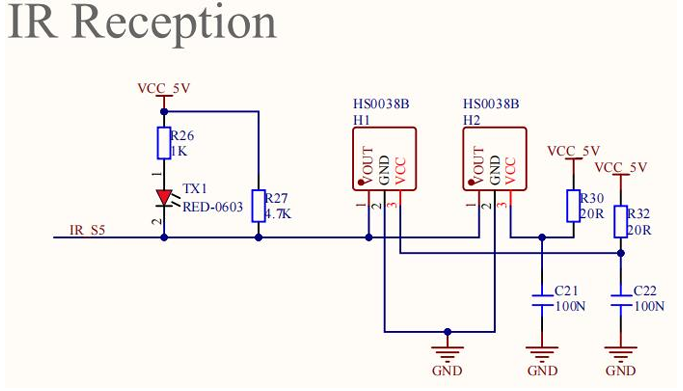
The IR receiver module has solely three pins, signal line (the infrared receiver is connected with the A3 pin of the single chip microcomputer), VCC and GND. It is distinctly convenient to connect and communicate with Keyestudio UNO PLUS development board and other microcontrollers.
2.Working Principle
The 38KHz carrier signal transmitted by the IR remote control is encoded by the coding chip in the remote, which is (NEC protocol) composed of a series of preamble code, user code, user inverse code, data code as well as data inverse code.
The time interval of the pulses is used to distinguish between 0 and 1 signals (560us low + 560us high is signal 0,560us low + 1680us high is signal 1),and the code is composed of these 0 and 1 signals.
The user code of the same remote control is unchanged, and the key pressed by the remote control can be distinguished by the data difference.
When pressing the key,the remote control sends out the infrared carrier signal. When the IR receiver obtains the signal,the program decodes the signal and determines which key is pressed.
The MCU is decoded by the received 01 signal to determine which key to press. In order to facilitate the reception of data, we have mounted the IR receiving heads on the car. Here we connect them to A3 of the UNO PLUS development board.
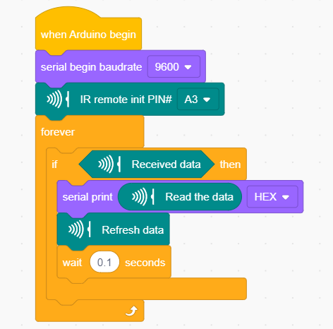
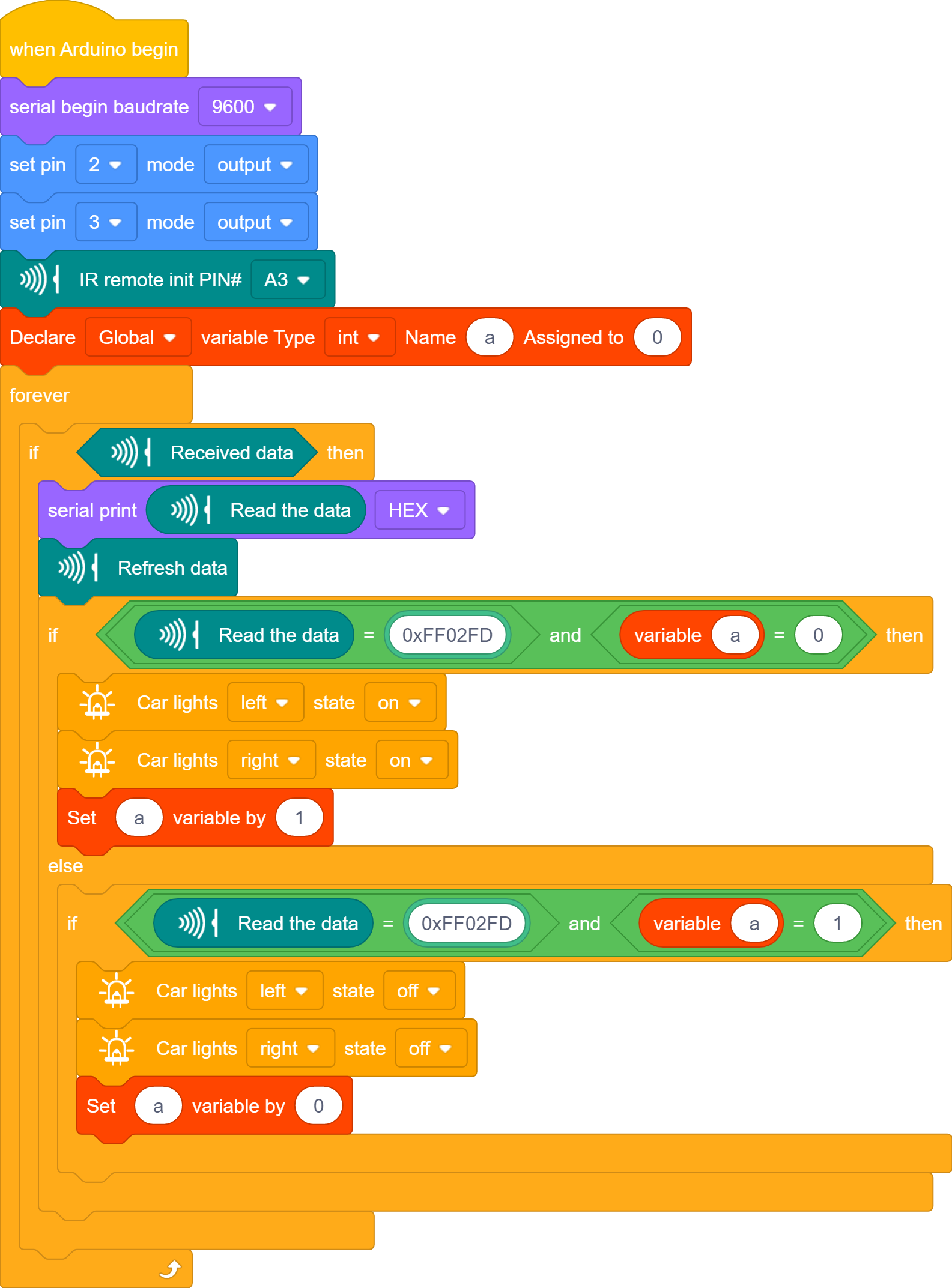
3.Test Code
4.Test Result
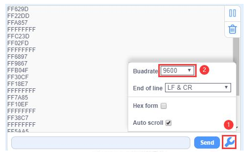
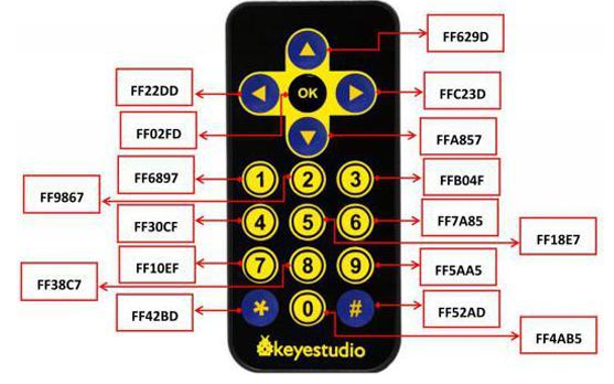
After uploading the test code successfully, turn the DIP switch to the ON end and power up and open the serial monitor and then click to set baud rate to 9600. Send signals with the remote control to the IR receiver sensor to see the key value of the corresponding button. If the button is pressed for a long time, garbled characters may appear.
5.Expanded Project Use a OK button to control the seven-color LED
After uploading the test code successfully, turn the DIP switch to the ON end and power up. When we use the remote control to press the OK button, the LED lights up, press it again, the LED will go off.