5.7 Temperaturregelsystem
5.7.1 DHT11 Temperatur- und Feuchtigkeitssensor
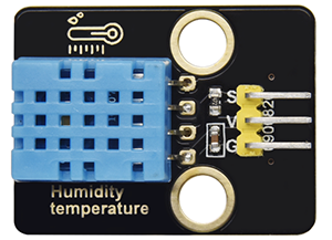
Der DHT11 Temperatur- und Feuchtigkeitssensor gibt digitale Signale aus. Er wendet die Prinzipien der analogen Signalerfassung und -umwandlung sowie der Temperatur- und Feuchtigkeitssensortechnologie an, wodurch er sich durch Langzeitstabilität und hohe Zuverlässigkeit auszeichnet. Außerdem integriert der Sensor einen hochpräzisen resistiven Feuchtigkeitssensor und einen resistiven thermosensitiven Temperatursensor und ist mit einem 8-Bit-Hochleistungs-MCU verbunden.
Öffnen Sie den Code 5.7.4Temperature-Control-System mit Arduino IDE
#include <dht11.h>
#define DHT11PIN 17

dht11 DHT11;

void setup()
{
  Serial.begin(9600);
  Serial.println("DHT11 TEST PROGRAM ");
  Serial.print("LIBRARY VERSION: ");
  Serial.println(DHT11LIB_VERSION);
  Serial.println();
}

void loop()
{
  Serial.println("\n");

  int chk = DHT11.read(DHT11PIN);

  Serial.print("Read sensor: ");
  switch (chk)
  {
    case DHTLIB_OK:
                Serial.println("OK");
                break;
    case DHTLIB_ERROR_CHECKSUM:
                Serial.println("Checksum error");
                break;
    case DHTLIB_ERROR_TIMEOUT:
                Serial.println("Time out error");
                break;
    default:
                Serial.println("Unknown error");
                break;
  }

  Serial.print("Humidity (%): ");
  Serial.println((float)DHT11.humidity, 2);

  Serial.print("Temperature (oC): ");
  Serial.println((float)DHT11.temperature, 2);

  Serial.print("Temperature (oF): ");
  Serial.println(Fahrenheit(DHT11.temperature), 2);

  Serial.print("Temperature (K): ");
  Serial.println(Kelvin(DHT11.temperature), 2);

  Serial.print("Dew Point (oC): ");
  Serial.println(dewPoint(DHT11.temperature, DHT11.humidity));

  Serial.print("Dew PointFast (oC): ");
  Serial.println(dewPointFast(DHT11.temperature, DHT11.humidity));

  delay(2000);
}

double Fahrenheit(double celsius)
{
        return 1.8 * celsius + 32;
}    //Convert Celsius degree to Fahrenheit degree

double Kelvin(double celsius)
{
        return celsius + 273.15;
}     //Convert Celsius degree to Kelvins

//Dew Point. The air is saturated and dews are produced under this temperature.
//Reference: http://wahiduddin.net/calc/density_algorithms.htm
double dewPoint(double celsius, double humidity)
{
        double A0= 373.15/(273.15 + celsius);
        double SUM = -7.90298 * (A0-1);
        SUM += 5.02808 * log10(A0);
        SUM += -1.3816e-7 * (pow(10, (11.344*(1-1/A0)))-1) ;
        SUM += 8.1328e-3 * (pow(10,(-3.49149*(A0-1)))-1) ;
        SUM += log10(1013.246);
        double VP = pow(10, SUM-3) * humidity;
        double T = log(VP/0.61078);   // temp var
        return (241.88 * T) / (17.558-T);
}

// Fast calculate the Dew Point, its speed is 5 times of dewPoint()
// Reference: http://en.wikipedia.org/wiki/Dew_point
double dewPointFast(double celsius, double humidity)
{
        double a = 17.271;
        double b = 237.7;
        double temp = (a * celsius) / (b + celsius) + log(humidity/100);
        double Td = (b * temp) / (a - temp);
        return Td;
}
Wählen Sie das Board ESP32 Dev Module und den COM-Port und laden Sie den Code hoch.

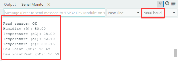
Testergebnis:
Öffnen Sie den seriellen Monitor und stellen Sie die Baudrate auf 9600 ein. Der serielle Monitor zeigt den aktuellen Temperatur- und Feuchtigkeitswert an.
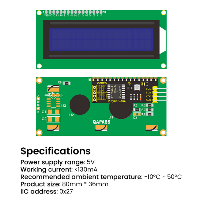
5.7.2 LCD 1602 Modul
Das LCD 1602 verfügt über eine standardmäßige 14-polige (ohne Hintergrundbeleuchtung) oder 16-polige (mit Hintergrundbeleuchtung) Schnittstelle, wodurch MCU-Pins gespart werden. Sein Display treibt den IC an, um die I2C-Steuerung zu realisieren.
Öffnen Sie den Code 5.7.2LCD1602 mit Arduino IDE.
#include <LiquidCrystal_I2C.h>

//Initialize LCD 1602, 0x27 is I2C address
LiquidCrystal_I2C lcd(0x27,16,2);

void setup() {
  //Initialize LCD
  lcd.init();
  // Turn the (optional) backlight off/on
  lcd.backlight();
  //lcd.noBacklight();

  //Set the position o dcursor
  lcd.setCursor(0, 0);
  //LCD prints
  lcd.print("HELLO WORLD 0");
  lcd.setCursor(0, 1);
  lcd.print("HELLO WORLD 1");

  //Clear displays
  // lcd.clear();
}

void loop() {

  // Turn the display on/off (quickly)
  //lcd.noDisplay();
  //lcd.display();

  // Turns the underline cursor on/off
  //lcd.noCursor();
  //lcd.cursor();

  // Turn on and off the blinking cursor
  // lcd.noBlink();
  // lcd.blink();

  // These commands scroll the display without changing the RAM
  //lcd.scrollDisplayLeft();
  //lcd.scrollDisplayRight();

  // This is for text that flows Left to Right
  //lcd.leftToRight();
  //lcd.rightToLeft();

  // This will 'right justify' text from the cursor
  //lcd.autoscroll();
  //lcd.noAutoscroll();

}
Wählen Sie das Board ESP32 Dev Module und den COM-Port und laden Sie den Code hoch.
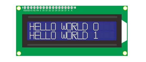
Testergebnis:
LCD1602 schaltet seine Hintergrundbeleuchtung ein und zeigt „HELLO WORLD 0“ und „HELLO WORLD 1“ an.
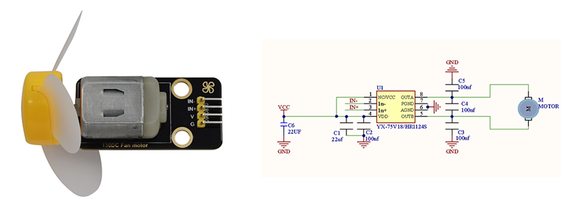
5.7.3 Motor und Lüfter
Der 130er Motor kann die Drehzahl über PWM einstellen. Dabei müssen zwei Pins zur Steuerung angeschlossen werden.
Öffnen Sie den Code 5.7.3Motor mit Arduino IDE.
#define MotorPin1 19  //(IN+)
#define MotorPin2 18  //(IN-)

void setup() {
  pinMode(MotorPin1, OUTPUT);
  pinMode(MotorPin2, OUTPUT);
}

void loop() {
  //corotation
  analogWrite(MotorPin1, 255); //Adjust the motor speed by modifying the analog value output range from 0-255
  analogWrite(MotorPin2, 0);
  delay(2000);
  //Stop Transition
  delay(200);
  analogWrite(MotorPin1, 0);
  analogWrite(MotorPin2, 0);
  delay(200);
  //reversal
  analogWrite(MotorPin1, 0);
  analogWrite(MotorPin