4. Assemble the Smart Farm Kit
Step 1 Install the ESP32 Board and the Relay Module
1.1 Required components

1.2

1.3

1.4

1.5

Step 2 Install the Fixing Frame for Battery Case and install the Feeding Cabin, connect the ESP32 board and the Relay Module
2.1 Required components

2.2
Assemble the wooden board X and O on bottom plate

2.3

2.4

2.5

2.6

2.7

2.8 Connect the ESP32 board and the Relay Module
Module |
Wire |
Pin |
|---|---|---|
Relay Module |
3PIN 20cm |
IO25 |
Module Pin |
Wire Color |
ESP32 Board Pin |
|---|---|---|
V |
RED |
V |
G |
BLACK |
G |
S |
YELLOW |
io25 |

2.9

Step 3 Install the Substructure of the house
3.1 Required components

3.2

3.3

3.4

3.5

3.6

3.7

3.8

3.9

3.10

3.11

Step 4 Install the Door of the Feeding Cabin
4.1 Required components

4.2 Set Servo to 180°
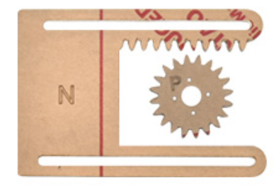
The acrylic sheet is packed separately, and it is recommended that you tear off its protective film to reduce the friction when it moves as a door.
4.3 Install Servo

4.4
Note: The screws need to be tightened to keep the servo stable, otherwise the door may get stuck

4.5
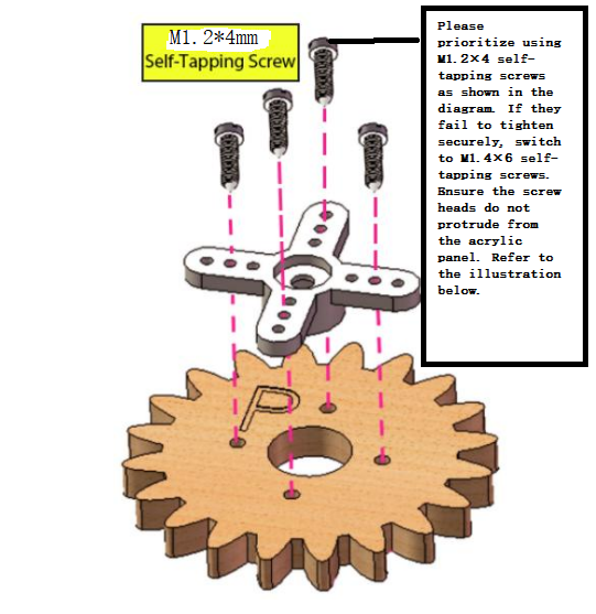
Install M1.4*6MM self-tapping screws as shown below

4.6
4.7

4.8
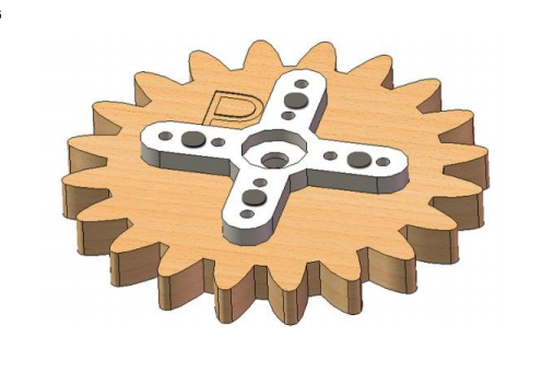
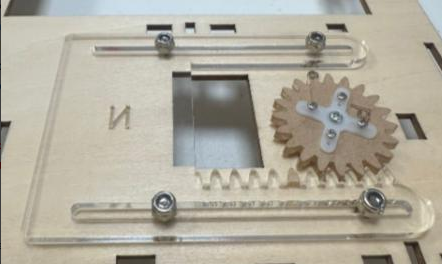
Do not turn the gear after it is installed on the servo. If you have already turned the gear you will need to readjust the servo angle to 180°.

4.9
NOTE: When installing the lid of the feeding box, its opening should be fully closed.

4.10

4.11

4.12

4.13 Test the door
Connect Servo to pin IO26 of the ESP32 board. Connect yellow to S, red to V, black to G.

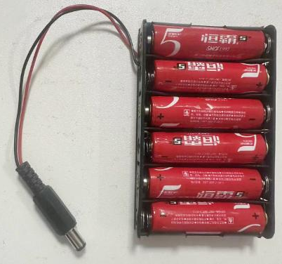
Connect 6 AA batteries to the DC 7-12V port of ESP32 board. (Batteries not included in the kit)

Upload the Test code
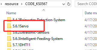
A. Connect the ESP32 board to the computer with the usb cable. Open the INO file inside the 6.1Servo folder with Arduino IDE.

B. Click on Tools, select “ESP32 Dev Module” for the board type in the drop-down menu bar, and select COM-XX for Port (According to the port assigned by your computer in the device manager)
C. Please make sure you have uploaded the ESP32Servo library and then upload the code. The door of the feeding cabin will open and close slowly.
NOTE: After uploading the code, ifthe door cannot be opened and closed and the servo is hot, please turn offthe powerimmediately.
check:
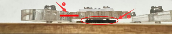
Whether the plastic door has good contact and force points with the gear structure of the servo.
Whether the tip of the fixing screw on the gear structure of the servo is stuck with the plastic shell of the servo. If so, please loosen the fixing screw a little to prevent its tip from contacting the servo.
Step 5 Install the LCD display and the DHT11 Sensor
5.1 Required components

5.2

5.3

5.4

5.5 Prototype

5.6 Wiring
Connect modules via Dupont wires.
Module |
Wire |
|---|---|
Temperature and Humidity Sensor |
3PIN 20cm |
Pay attention to the color of the Dupont wire:
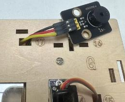
For temperature and humidity sensor, connect yellow to S, red to V, black to G.

5.7
Module |
Wire |
|---|---|
LCD 1602 |
4PIN (Black-Red-Blue-Green) |
For the LCD display, connect green to SCL, blue to SDA, red to VCC, black to GND.

Step 6 Install the Ultrasonic Module
6.1 Required components

6.2

6.3

6.4 Wiring
Module |
Wire |
|---|---|
Ultrasonic module |
4PIN (Black-Green-Blue-Red) |
Pay attention to the color of the Dupont wire: For the ultrasonic module, connect blue to TRIG,green to ECHO, red to VCC, black to GND.

Step 7 Install the PIR Motion Sensor and Button Module
7.1 Required components

7.2

7.3

7.4 Wiring
Connect modules via Dupont wires.
Module |
Wire |
|---|---|
PIR Motion Sensor |
3PIN 15cm |
Button Module |
3PIN 15cm |
Pay attention to the color of the Dupont wire: Connect yellow to S, red to V, black to G.

Step 8 Install the Walls of the House
8.1 Required components

8.2

8.3

8.4

8.5

8.6

8.7

8.8 Prototype

8.9 Wiring
Module |
Wire |
|---|---|
Fan |
4PIN Divided (Black-Red-Blue-Green) |
Steam Sensor |
3PIN 15cm |
Photoresistor |
3PIN 15cm |
Pay attention to the color of the Dupont wire for the Fan:
Module Pin |
Wire Color |
ESP32 Board Pins |
|---|---|---|
IN- |
GREEN |
io18 |
IN+ |
BLUE |
io19 |
V |
RED |
V |
G |
BLACK |
G |
For Steam Sensor and Photoresistor: Connect yellow to S, red to V, black to G.

Step 9 Install the Roof of the house
9.1 Required components

9.2

9.3

9.4 Keep the wires organized

Step 10 Install the House and Ground
10.1 Required components

10.2

10.3

10.4 Bottom View

10.5

10.6 Arrange the wires

10.7

Step 11 Wiring the House
11.1
Pay attention to the color of the Dupont wire: Connect yellow to S, red to V, black to G.
NO. |
Components |
Wires |
ESP32 Board Pins |
|---|---|---|---|
1 |
Fan |
4pin, Divided Bla ck-Red-Blue-Green |
io18(IN-) \ io19(IN+) |
2 |
PIR Motion Sensor |
3pin 15cm |
io23 |
3 |
Button |
3pin 15cm |
io5 |
4 |
Ultrasonic Module |
4pin,Divided Bla ck-Green-Blue-Red |
D12(TRIG) D13(ECHO) |
5 |
LCD 1602 |
4pin, Connected |
I2C |
6 |
Temperature and Humidity Sensor |
3pin 20cm |
io17 |
7 |
Steam Sensor |
3pin 15cm |
io35 |
8 |
Photoresistor |
3pin 15cm |
io34 |
9 |
Servo |
– |
io26 |
10 |
Buzzer |
3pin 20cm |
io16 |
11 |
LED |
3pin 20cm |
io27 |
12 |
Water Level Sensor |
3pin 25cm |
io33 |
13 |
Soil Humidity Sensor |
3pin 20cm |
io32 |
14 |
Water Pump |
3pin 20cm |
io25 |
11.2 Fan
Pass the Dupont wire connected to the fan through the hole marked 30 on the wooden board.
Components |
Wire |
ESP32 Board Pins |
|---|---|---|
Fan |
4PIN Divided (Black-Red-Blue-Green) |
io18(IN-), io19(IN+) |
Module Pin |
Wire Color |
ESP32 Board Pins |
|---|---|---|
IN- |
GREEN |
io18 |
IN+ |
BLUE |
io19 |
V |
RED |
V |
G |
BLACK |
G |

11.3 PIR Motion Sensor
Pass the Dupont wire connected to the PIR motion sensor through the hole marked 24 on the wooden board.
Component |
Wire |
ESP32 Board Pin |
|---|---|---|
PIR Motion Sensor |
3PIN 15cm |
io23 |
Connect red to V, black to G, yellow to S.
Module Pin |
Wire Color |
ESP32 Board Pin |
|---|---|---|
V |
RED |
V |
G |
BLACK |
G |
S |
YELLOW |
io23 |

11.4 Button Module
Pass the Dupont wire connected to the button module through the hole marked 25 on the wooden board.
Component |
Wire |
ESP32 Board Pin |
|---|---|---|
Button |
3PIN 15cm |
io5 |
Connect red to V, black to G, yellow to S.
Module Pin |
Wire Color |
ESP32 Board Pin |
|---|---|---|
V |
RED |
V |
G |
BLACK |
G |
S |
YELLOW |
io5 |

11.5 Ultrasonic Module
Component |
Wire |
ESP32 Board Pins |
|---|---|---|
Ultrasonic Module |
4PIN Divided ( Black-Green-Blue-Red) |
io13(ECHO), io12(TRIG) |
Connect red to V, black to G, blue to io12, green to io13.
Module Pin |
Wire Color |
ESP32 Board Pin |
|---|---|---|
V |
RED |
V (io12) |
G |
BLACK |
G (io12) |
ECHO |
GREEN |
io13 |
TRIG |
BLUE |
io12 |

11.6 LCD 1602
Component |
Wire |
ESP32 Board Pins |
|---|---|---|
LCD1602 |
4PIN Connected (Black-Red-Blue-Green) |
I2C |
Connect red to V, black to G, blue to SDA, green to SCL.
Module Pin |
Wire Color |
ESP32 Board Pin |
|---|---|---|
V |
RED |
V |
G |
BLACK |
G |
SCL |
GREEN |
SCL |
SDA |
BLUE |
SDA |

11.7 Temperature and Humidity Sensor
Pass the Dupont wire connected to the button module through the hole marked 20 on the wooden board.
Component |
Wire |
ESP32 Board Pins |
|---|---|---|
Temperature and Humidity Sensor |
3PIN 20cm |
io17 |
Connect red to V, black to G, yellow to io17.
Module Pin |
Wire Color |
ESP32 Board Pin |
|---|---|---|
V |
RED |
V |
G |
BLACK |
G |
S |
YELLOW |
io17 |

11.8 Steam Sensor
Component |
Wire |
ESP32 Board Pin |
|---|---|---|
Steam Sensor |
3PIN 15cm |
io35 |
Connect red to V, black to G, yellow to io35.
Module Pin |
Wire Color |
ESP32 Board Pin |
|---|---|---|
V |
RED |
V |
G |
BLACK |
G |
S |
YELLOW |
io35 |

11.9 Photoresistor
Component |
Wire |
ESP32 Board Pin |
|---|---|---|
Photoresistor |
3PIN 15cm |
io34 |
Connect red to V, black to G, yellow to io34.
Module Pin |
Wire Color |
ESP32 Board Pin |
|---|---|---|
V |
RED |
V |
G |
BLACK |
G |
S |
YELLOW |
io34 |

11.10 Servo
Pass the wire of Servo through the Hole 15, and then connect it to ESP32 board.
Component |
Wire |
ESP32 Board Pin |
|---|---|---|
Servo |
3PIN |
io26 |
Connect red to V, black to G, yellow to io26.
ESP32 Board Pin |
Wire Color |
|---|---|
V |
RED |
G |
BLACK |
IO26 |
YELLOW |

11.11 Buzzer
Pass the wire of Buzzer through the Hole 17, and then connect it to ESP32 board.
Component |
Wire |
ESP32 Board Pin |
|---|---|---|
Buzzer |
3PIN 20cm |
io16 |
Connect red to V, black to G, yellow to io16.
Module Pin |
Wire Color |
ESP32 Board Pin |
|---|---|---|
V |
RED |
V |
G |
BLACK |
G |
S |
YELLOW |
io16 |

11.12 LED
Pass the wire of LED through the Hole 7, and then connect it to ESP32 board.
Component |
Wire |
ESP32 Board Pin |
|---|---|---|
LED |
3PIN 20cm |
io27 |
Connect red to V, black to G, yellow to io27.
Module Pin |
Wire Color |
ESP32 Board Pin |
|---|---|---|
V |
RED |
V |
G |
BLACK |
G |
S |
YELLOW |
io27 |

11.13 Water Lever Sensor
Pass the wire of water level sensor through the Hole 13, and then connect it to ESP32 board.
Component |
Wire |
ESP32 Board Pin |
|---|---|---|
Water Lever Sensor |
3PIN 25cm |
io33 |
Connect red to V, black to G, yellow to io33.
Module Pin |
Wire Color |
ESP32 Board Pin |
|---|---|---|
V |
RED |
V |
G |
BLACK |
G |
S |
YELLOW |
io33 |

11.14 Soil Humidity Sensor
Pass the wire of soil humidity sensor through the Hole 11, and then connect it to ESP32 board.
Component |
Wire |
ESP32 Board Pin |
|---|---|---|
Soil Humidity Sensor |
3PIN 20cm |
io32 |
Connect red to V, black to G, yellow to io32.
Module Pin |
Wire Color |
ESP32 Board Pin |
|---|---|---|
V |
RED |
V |
G |
BLACK |
G |
S |
YELLOW |
io32 |

11.15 Relay Module
Component |
Wire |
ESP32 Board Pin |
|---|---|---|
Relay Module |
3PIN |
io25 |
Module Pin |
Wire Color |
ESP32 Board Pin |
|---|---|---|
V |
RED |
V |
G |
BLACK |
G |
S |
YELLOW |
io25 |
Pass the wire of Water Pump through the Hole 11 in the way as shown below:

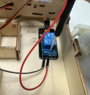
The red wire of the water pump is connected to the middle terminal of the relay module, and the black wire is connected to the GND of the ESP32 board.
In addition, you need to use a Dupont wire to connect the left terminal of the relay module to the 3.3V of the ESP32.


Insert the male terminal of the Dupont wire into the female terminal of the relay module and tighten it with a screwdriver.
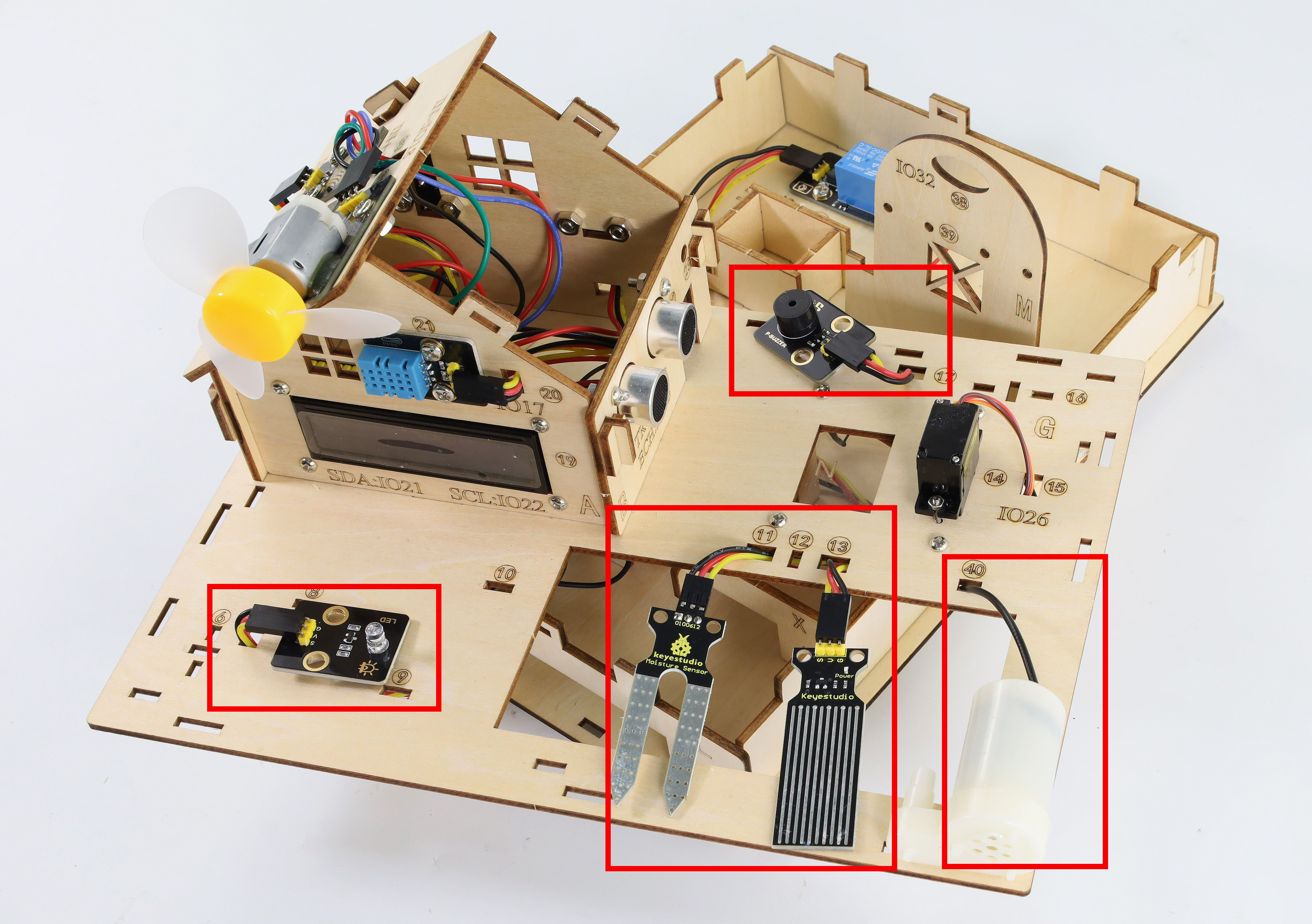
After the above steps, note that all the wiring has been finished. And wires of the LED, water level sensor, soil humidity sensor, buzzer and relay water pump have respectively passed through the holes of 7, 11, 13, 17 and 40 carved on the basswood board, preparing for the subsequent installation.
Step 12 Install the house and foundation
12.1 Required components

12.2

12.3

12.4

12.5

Step 13 Install the Plastic Sinks
13.1 Required components

13.2

13.3

Step 14 Install the soil module and water level module
14.1 Required components

14.2

14.3

14.4

14.5

14.6

14.7

Step 15 Install fence
15.1 Required components

15.2

15.3

15.4

Step 16 Install the Buzzer and the Led Module
16.1 Required components

16.2

16.3

16.4

Step 17 Decorate the House
17.1 Required components

17.2

17.3

Step 18 Install Solar Panel
18.1 Required components

18.2

18.3

18.4

18.5
Install the LED light of the solar panel into this hole.

18.6
Use a sticker to secure its wires to the wall

18.7

18.8

18.9

18.10

Step 19 Install Battery Case
19.1 Required components

19.2
Install 6 AA batteries(Not included in the kit)
19.3

19.4
