5.1 Lighting System
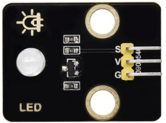
5.1.1 Light up an LED
Open the 5.1.1Blink code with Arduino IDE.
#define LED_BUILTIN 27  //LED pins

void setup() {
  // initialize digital pin LED_BUILTIN as an output.
  pinMode(LED_BUILTIN, OUTPUT);
}

// the loop function runs over and over again forever
void loop() {
  digitalWrite(LED_BUILTIN, HIGH);  // turn the LED on (HIGH is the voltage level)
  delay(1000);                      // wait for a second
  digitalWrite(LED_BUILTIN, LOW);   // turn the LED off by making the voltage LOW
  delay(1000);                      // wait for a second
}
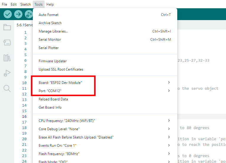
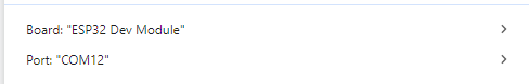
Choose the ESP32 Dev Module board and COM port, and upload the code.
Test Result:
LED blinks per second, because io27 on ESP32 board outputs high and low level alternatively every second.
Power Level |
Result |
|---|---|
HIGH |
LED ON |
LOW |
LED OFF |
5.1.2 Controlthe LED with PWM
Open the 5.1.2PWM code with Arduino IDE.
#define led 27    //Define LED pin

void setup(){
  pinMode(led, OUTPUT);  //Set pin to output mode
}

void loop(){
  for(int i=0; i<255; i++)  //for loop statement. Constantly increase variable i till 255, exit the loop
  {
    analogWrite(led, i);  //PWM output, used to control the brightness of LED
    delay(3);
  }
  for(int i=255; i>0; i--)  //for loop statement. Constantly decrease variable i till 0, exit the loop
  {
    analogWrite(led, i);
    delay(3);
  }
}
Choose the ESP32 Dev Module board and COM port, and upload the code.
Test Result:
At an appropriate signal frequency, PWM changes effective output voltage by changing the duty cycle in one period. In plain English, within a specified time, the more high level the IO port outputs, the greater PWM value is, and the lighter LED will be.
The LED module willslowly light up from dark to bright, and then from dark to bright.

5.1.3 Read the digital value of Button
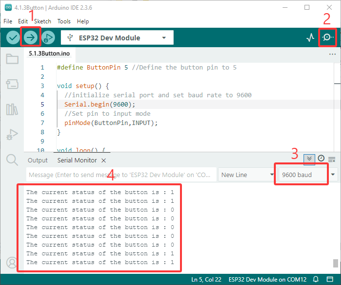
Open the 5.1.3Button code with Arduino IDE.
#define ButtonPin 5 //Define the button pin to 5

void setup() {
  //initialize serial port and set baud rate to 9600
  Serial.begin(9600);
  //Set pin to input mode
  pinMode(ButtonPin,INPUT);
}

void loop() {
  //Define a value as the read button value
  int ReadValue = digitalRead(ButtonPin);
  //Serial port prints the defined value
  Serial.print("The current status of the button is : ");
  Serial.println(ReadValue);
  delay(500);
}
Choose the ESP32 Dev Module board and COM port, and upload the code.
Test Result:
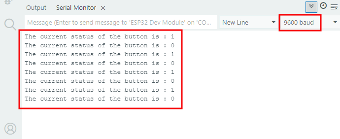
Open serial monitor and set the baud rate to 9600.
When the button is released, the value is 1; if you press the button, it becomes 0.
The principle ofthe button module is a circuit controlled by this button.
When the button is pressed, the circuit is closed so that current passes through the button to GND, which causes the digital input pin to detect a low level.
When the button is released, the circuit is cut and pin level increases due to a pull-up resistor, which makes the digital pin to detect a high level.
5.1.4 Auto-locking Button
Open the 5.1.4 Self-Locking_Button code with Arduino IDE.
#define ButtonPin 5 //Define the button pin
int value = 0;      //Define a value to determine the status of button

void setup() {
  //Initialize the serial port and set baud rate to 9600
  Serial.begin(9600);
  //Set the pin to inpu tmode
  pinMode(ButtonPin,INPUT);
}

void loop() {
  //Define a value as the read button value
  int ReadValue = digitalRead(ButtonPin);
  //Detect whether the button is pressed
  if (ReadValue == 0) {
    //Eliminate the button shake
    delay(10);
    if (ReadValue == 0) {
      value = !value;
      Serial.print("The current status of the button is : ");
      Serial.println(value);
    }
    //Detect again whether the button is still pressed
    //Pressed: execute the loop; Released: exit the loop to next step
    while (digitalRead(ButtonPin) == 0);
  }
}
Choose the ESP32 Dev Module board and COM port, and upload the code.
Test Result:
Open serial monitor and set the baud rate to 9600.
When you press the button once, 1 will be displayed. If you press button for the second time, the value becomes 0. Now, a common button boasts the function of an auto-locking one.
5.1.5 Use the button to control LED module
Open the 5.1.5 Lighting-System code with Arduino IDE.
#define ButtonPin 5   //Define a button pin
#define LED       27  //Define LED pin
int value = 0;        //Define a value to detect button status

void setup() {
  //initialize serial port and set baud rate to 9600
  Serial.begin(9600);
  //Set pin to input mode
  pinMode(ButtonPin,INPUT);
  //Set pin to output mode
  pinMode(LED,OUTPUT);
}

void loop() {
  //Define a value as the read button value
  int ReadValue = digitalRead(ButtonPin);
  //Detect whether the button is pressed
  if (ReadValue == 0) {
    //Eliminate the button shake
    delay(10);
    if (ReadValue == 0) {
      value = !value;
      //Detect the button status, press once to light up LED, press again to turn off LED, in a loop
      if(value) {
        digitalWrite(LED,HIGH);
      }else{
        digitalWrite(LED,LOW);
      }
    }
    //Detect the button status again
    //Pressed: execute the loop; Released: exit the loop to next step
    while (digitalRead(ButtonPin) == 0);
  }
}
Choose the ESP32 Dev Module board and COM port, and upload the code.
Test Result:
When you press the button once, LED lights up; if you press again, LED turns off. This operation is a loop, which is consistent with the lighting principle in reality.
