Project 11: Active Buzzer

1. Overview
In this kit, it contains an active buzzer module and a power amplifier module (the principle is equivalent to a passive buzzer). In this experiment, we control the active buzzer to emit sounds. Since it has its own oscillating circuit, the buzzer will automatically sound if given large voltage.
2. Working Principle
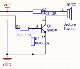
From the schematic diagram, the pin of buzzer is connected to a resistor R2 and another port is linked with a NPN triode Q1. So, if this triode Q1 is powered, the buzzer will sound.
If the base electrode of the triode connected to the R1 resistor is a high level, the triode Q1 will be connected. If the base electrode is pulled down by the resistor R3, the triode is disconnected.
When we output a high level from the IO port to the triode, the buzzer will emit sounds; if outputting low levels, the buzzer won’t emit sounds.
3. Components

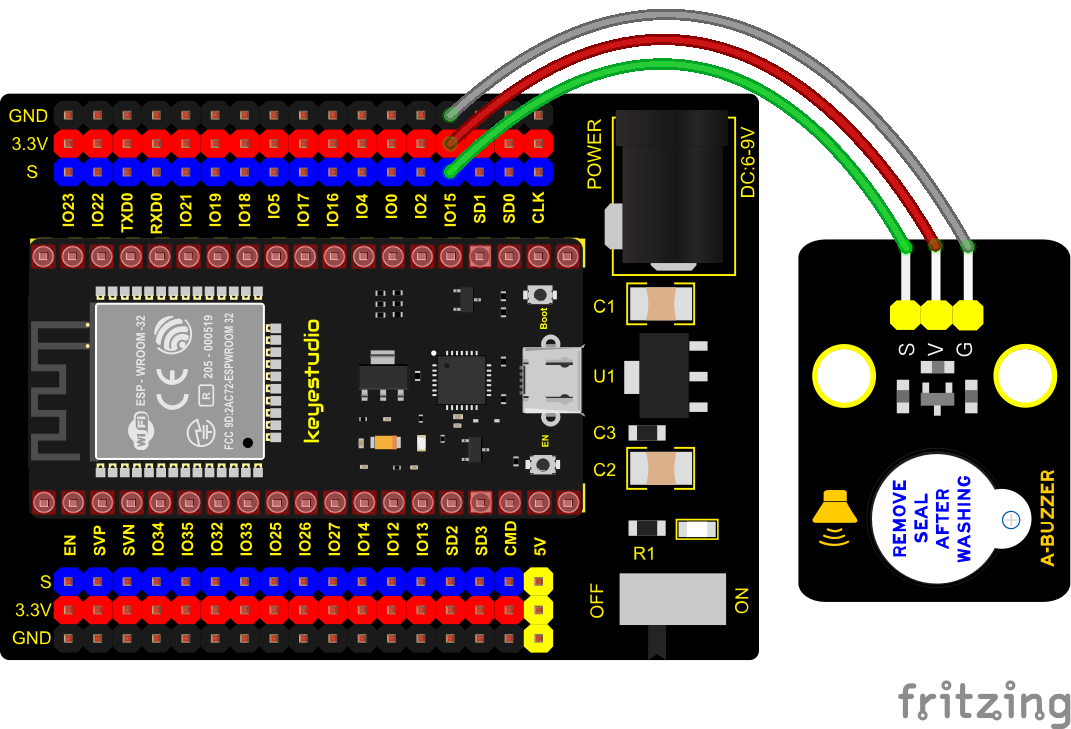
4. Connection Diagram
5. Test Code
from machine import Pin
import time

buzzer = Pin(15, Pin.OUT)
while True:
    buzzer.value(1)
    time.sleep(1)
    buzzer.value(0)
    time.sleep(1)
6. Code Explanation
In the experiment, we set the pin to GPIO15. When setting to high, the active buzzer will beep. When setting to low, the active buzzer will stop emitting sounds.
7. Test Result
Connect the wires according to the experimental wiring diagram and power on. Click  “Run current script”, the code starts executing. The active buzzer will emit sound for 1 s, and stop for 1 s. Press “Ctrl+C”or click
 “Stop/Restart backend”to exit the program.