Project 12 Ultrasonic Following Tank

Description
In project 11, we made an obstacle avoidance car. In fact, we only need to alter a test code to transform an obstacle avoidance car into a following car. In this lesson, we will make an ultrasonic following robot. The ultrasonic sensor detects the distance between smart car and the obstacle to drive tank car to move.
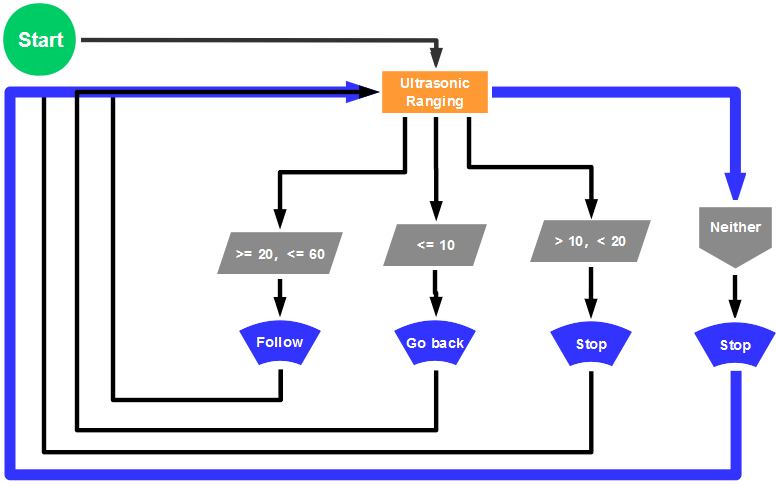
The specific logic of ultrasonic follow robot is as shown below:
Detection |
Measured distance of front obstacles |
Distance (unit: cm) |
|---|---|---|
Settings |
Servo angle 90° |
|
8X16 LED panel shows the icon “V” |
||
If |
20≤ distance ≤60 |
|
Status |
Go front(set PWM to 200) |
|
If |
10<distance<20 |
|
distance>60 |
||
Status |
stop |
|
If |
distance ≤10 |
|
Status |
Stop(set PWM to 200) |
Flow chart
Connection Diagram

Wire-up note:
1.8x16 LED panel |
V5 Sensor Shield |
|
|---|---|---|
GND |
→ |
-(GND) |
VCC |
→ |
+(VCC) |
SDA |
→ |
SDA |
SCL |
→ |
SCL |
Test Code
 /*
 keyestudio Mini Tank Robot v2.0
 lesson 12
 ultrasonic follow tank
 http://www.keyestudio.com
*/
//Array, used to store the data of the pattern, can be calculated by yourself or obtained from the modulus tool
unsigned char start01[] = {0x01,0x02,0x04,0x08,0x10,0x20,0x40,0x80,0x80,0x40,0x20,0x10,0x08,0x04,0x02,0x01};
unsigned char front[] = {0x00,0x00,0x00,0x00,0x00,0x24,0x12,0x09,0x12,0x24,0x00,0x00,0x00,0x00,0x00,0x00};
unsigned char back[] = {0x00,0x00,0x00,0x00,0x00,0x24,0x48,0x90,0x48,0x24,0x00,0x00,0x00,0x00,0x00,0x00};
unsigned char left[] = {0x00,0x00,0x00,0x00,0x00,0x00,0x44,0x28,0x10,0x44,0x28,0x10,0x44,0x28,0x10,0x00};
unsigned char right[] = {0x00,0x10,0x28,0x44,0x10,0x28,0x44,0x10,0x28,0x44,0x00,0x00,0x00,0x00,0x00,0x00};
unsigned char STOP01[] = {0x2E,0x2A,0x3A,0x00,0x02,0x3E,0x02,0x00,0x3E,0x22,0x3E,0x00,0x3E,0x0A,0x0E,0x00};
unsigned char clear[] = {0x00,0x00,0x00,0x00,0x00,0x00,0x00,0x00,0x00,0x00,0x00,0x00,0x00,0x00,0x00,0x00};
#define SCL_Pin  A5  //Set clock pin to A5
#define SDA_Pin  A4  //Set data pin to A4

#define ML_Ctrl 13  //define the direction control pin of left motor
#define ML_PWM 11   //define PWM control pin of left motor
#define MR_Ctrl 12  //define the direction control pin of right motor
#define MR_PWM 3   //define PWM control pin of right motor
#define Trig 5  //ultrasonic trig Pin
#define Echo 4  //ultrasonic echo Pin
int distance;
int pulsewidth;
#define servoPin 9  //servo Pin
void setup(){
  Serial.begin(9600);
  pinMode(SCL_Pin,OUTPUT);
  pinMode(SDA_Pin,OUTPUT);
  matrix_display(clear); //Clear the display
  matrix_display(start01);  //display start pattern
  pinMode(servoPin, OUTPUT);
  procedure(90); //set servo to 90°
  pinMode(Trig, OUTPUT);
  pinMode(Echo, INPUT);
  pinMode(ML_Ctrl, OUTPUT);
  pinMode(ML_PWM, OUTPUT);
  pinMode(MR_Ctrl, OUTPUT);
  pinMode(MR_PWM, OUTPUT);
}
void loop(){
  distance = checkdistance();  //assign the distance detected by ultrasonic sensor to distance
  if (distance >= 20 && distance <= 60) //range to go front
  {
    Car_front();
  }
  else if (distance > 10 && distance < 20)  //range to stop
  {
    Car_Stop();
  }
  else if (distance <= 10)  //range to go back
  {
    Car_back();
  }
  else  //other situations, stop
  {
    Car_Stop();
  }
}
/***********the function for motor running****************/
void Car_front()
{
  digitalWrite(MR_Ctrl,LOW);
  analogWrite(MR_PWM,200);
  digitalWrite(ML_Ctrl,LOW);
  analogWrite(ML_PWM,200);
}
void Car_back()
{
  digitalWrite(MR_Ctrl,HIGH);
  analogWrite(MR_PWM,200);
  digitalWrite(ML_Ctrl,HIGH);
  analogWrite(ML_PWM,200);
}
void Car_left()
{
  digitalWrite(MR_Ctrl,LOW);
  analogWrite(MR_PWM,200);
  digitalWrite(ML_Ctrl,HIGH);
  analogWrite(ML_PWM,200);
}
void Car_right()
{
  digitalWrite(MR_Ctrl,HIGH);
  analogWrite(MR_PWM,200);
  digitalWrite(ML_Ctrl,LOW);
  analogWrite(ML_PWM,200);
}
void Car_Stop()
{
  digitalWrite(MR_Ctrl,LOW);
  analogWrite(MR_PWM,0);
  digitalWrite(ML_Ctrl,LOW);
  analogWrite(ML_PWM,0);
}

/******************dot matrix********************/
// the function for dot matrix display
void matrix_display(unsigned char matrix_value[])
{
  IIC_start(); // call the function that data transmission start
  IIC_send(0xc0);  //Choose address

  for(int i = 0;i < 16;i++) //pattern data has 16 bits
  {
     IIC_send(matrix_value[i]); //data to convey patterns
  }

  IIC_end();   //end to convey data pattern

  IIC_start();
  IIC_send(0x8A);  //select pulse width4/16, control display
  IIC_end();
}

//The condition starting to transmit data
void IIC_start()
{
  digitalWrite(SCL_Pin,HIGH);
  delayMicroseconds(3);
  digitalWrite(SDA_Pin,HIGH);
  delayMicroseconds(3);
  digitalWrite(SDA_Pin,LOW);
  delayMicroseconds(3);
}

// transmit data
void IIC_send(unsigned char send_data)
{
  for(char i = 0;i < 8;i++)  //Each byte has 8 bits
  {
      digitalWrite(SCL_Pin,LOW);  //pull down clock pin SCL Pin to change the signals of SDA
delayMicroseconds(3);
      if(send_data & 0x01)  //set high and low level of SDA_Pin according to 1 or 0 of every bit
      {
        digitalWrite(SDA_Pin,HIGH);
      }
      else
      {
        digitalWrite(SDA_Pin,LOW);
      }
      delayMicroseconds(3);
      digitalWrite(SCL_Pin,HIGH); //pull up clock pin SCL_Pin to stop transmitting data
      delayMicroseconds(3);
      send_data = send_data >> 1;  // detect bit by bit, so move the data right by one
  }
}
//The sign that data transmission ends
void IIC_end()
{
  digitalWrite(SCL_Pin,LOW);
  delayMicroseconds(3);
  digitalWrite(SDA_Pin,LOW);
  delayMicroseconds(3);
  digitalWrite(SCL_Pin,HIGH);
  delayMicroseconds(3);
  digitalWrite(SDA_Pin,HIGH);
  delayMicroseconds(3);
}
/***************end dot matrix display******************/
//The function to control servo
void procedure(int myangle) {
  for (int i = 0; i <= 50; i = i + (1)) {
    pulsewidth = myangle * 11 + 500;
    digitalWrite(servoPin,HIGH);
    delayMicroseconds(pulsewidth);
    digitalWrite(servoPin,LOW);
    delay((20 - pulsewidth / 1000));
  }}
//The function to control ultrasonic sensor function controlling ultrasonic
float checkdistance() {
  digitalWrite(Trig, LOW);
  delayMicroseconds(2);
  digitalWrite(Trig, HIGH);
  delayMicroseconds(10);
  digitalWrite(Trig, LOW);
  float distance = pulseIn(Echo, HIGH) / 58.20;  //58.20, that is , 2*29.1=58.2
  delay(10);
  return distance;
}
//****************************************************************
Test Result
Upload code successfully, DIP switch is dialed to the right end, the servo rotates to 90°, “V” is shown on 8X16 LED panel and smart car moves as the obstacle moves.