Project 13 IR Remote Robot Tank

Description
IR remote control is one of most ubiquitous control, applied in TV, electric fan and some household appliances. In this project, we will make an IR remote smart car. Since we’ve known every key value on IR remote control, we could control smart car via and display the patterns on dot matrix via corresponding key value.
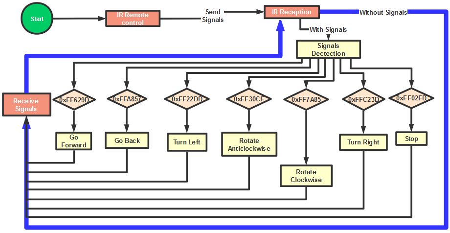
The specific logic of infrared remote control robot is shown below:
Initial setup |
Servo angle 90° |
|
|---|---|---|
8X16 LED matrix panel shows an icon “V” |
||
Remote control |
Key value |
Key state |
|
FF629D |
Go front(PWM set to 200) |
8X16 LED panel shows front icon |
||
|
FFA857 |
Go back(PWM set to 200) |
8X16 LED panel shows back icon |
||
|
FF22DD |
Turn left |
8X16 LED panel shows leftward icon |
||
|
FFC23D |
Turn right |
8X16 LED panel shows rightward icon |
||
|
FF02FD |
Stop |
8X16 LED panel shows “STOP” |
||
|
FF30CF |
Rotate to left(PWM set to 200) |
8X16 LED panel shows leftward icon |
||
|
FF7A85 |
Rotate to right(PWM set to 200) |
8X16 LED panel shows rightward icon |


Flow Chart
Connection Diagram
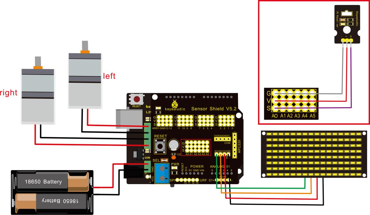
Attention:GND,VCC, SDA, SCL of 8x16 LED panel are respectively linked with-(GND), +(VCC), SDA ,SCL. And “-”、“+” and S of IR receiver module are attached to G(GND), V(VCC) and A0 on sensor shield. On the condition of insufficient digital ports, the analog ports can be treat as digital ports. A0 equals to digital 14, A1 is like digital 15.
Test Code
/*
 keyestudio Mini Tank Robot v2.0
 lesson 13
 IR remote tank
 http://www.keyestudio.com
*/

#include <IRremoteTank.h>
IRrecv irrecv(A0);  //set IRrecv irrecv to A0
decode_results results;
long ir_rec;  //save the IR value received

//Array, used to store the data of the pattern, can be calculated by yourself or obtained from the modulus tool
unsigned char start01[] = {0x01,0x02,0x04,0x08,0x10,0x20,0x40,0x80,0x80,0x40,0x20,0x10,0x08,0x04,0x02,0x01};
unsigned char front[] = {0x00,0x00,0x00,0x00,0x00,0x24,0x12,0x09,0x12,0x24,0x00,0x00,0x00,0x00,0x00,0x00};
unsigned char back[] = {0x00,0x00,0x00,0x00,0x00,0x24,0x48,0x90,0x48,0x24,0x00,0x00,0x00,0x00,0x00,0x00};
unsigned char left[] = {0x00,0x00,0x00,0x00,0x00,0x00,0x44,0x28,0x10,0x44,0x28,0x10,0x44,0x28,0x10,0x00};
unsigned char right[] = {0x00,0x10,0x28,0x44,0x10,0x28,0x44,0x10,0x28,0x44,0x00,0x00,0x00,0x00,0x00,0x00};
unsigned char STOP01[] = {0x2E,0x2A,0x3A,0x00,0x02,0x3E,0x02,0x00,0x3E,0x22,0x3E,0x00,0x3E,0x0A,0x0E,0x00};
unsigned char clear[] = {0x00,0x00,0x00,0x00,0x00,0x00,0x00,0x00,0x00,0x00,0x00,0x00,0x00,0x00,0x00,0x00};
#define SCL_Pin  A5  //Set clock pin to A5
#define SDA_Pin  A4  //Set data pin to A4

#define ML_Ctrl 13  //define the direction control pin of left motor
#define ML_PWM 11   //define PWM control pin of left motor
#define MR_Ctrl 12  //define the direction control pin of right motor
#define MR_PWM 3    //define PWM control pin of right motor

#define servoPin 9 //pin of servo
int pulsewidth; //save the pulse width value of servo

void setup(){
  Serial.begin(9600);
  irrecv.enableIRIn();  //Initialize the IR reception library

  pinMode(ML_Ctrl, OUTPUT);
  pinMode(ML_PWM, OUTPUT);
  pinMode(MR_Ctrl, OUTPUT);
  pinMode(MR_PWM, OUTPUT);

  pinMode(SCL_Pin,OUTPUT);
  pinMode(SDA_Pin,OUTPUT);
  matrix_display(clear); //Clear Screen
  matrix_display(start01);  //show start picture

  pinMode(servoPin, OUTPUT);
  procedure(90);  //Servo rotates to 90°
}

void loop(){
  if (irrecv.decode(&results)) //receive the IR remote value
  {
    ir_rec=results.value;
    String type="UNKNOWN";
    String typelist[14]={"UNKNOWN", "NEC", "SONY", "RC5", "RC6", "DISH", "SHARP", "PANASONIC", "JVC", "SANYO", "MITSUBISHI", "SAMSUNG", "LG", "WHYNTER"};
    if(results.decode_type>=1&&results.decode_type<=13){
      type=typelist[results.decode_type];
    }
    Serial.print("IR TYPE:"+type+"  ");
    Serial.println(ir_rec,HEX);
    irrecv.resume();
  }

  if (ir_rec == 0xFF629D) //Go forward
  {
    Car_front();
    matrix_display(front);  //Display front image
  }
  if (ir_rec == 0xFFA857)  //Robot car goes back
  {
    Car_back();
    matrix_display(front);  //Go back
  }
  if (ir_rec == 0xFF22DD)   //Robot car turns left
  {
    Car_T_left();
    matrix_display(left);  //Display left-turning image
  }
  if (ir_rec == 0xFFC23D)   //Robot car turns right
  {
    Car_T_right();
    matrix_display(right);  //Display right-turning image
  }
  if (ir_rec == 0xFF02FD)   //Robot car stops
  {
    Car_Stop();
    matrix_display(STOP01);  //show stop image
  }
  if (ir_rec == 0xFF30CF)   //robot car rotates anticlockwise
  {
    Car_left();
    matrix_display(left);  //show anticlockwise rotation picture
  }
  if (ir_rec == 0xFF7A85)  //robot car rotates clockwise
  {
    Car_right();
    matrix_display(right);  //show clockwise rotation picture
 }
}
/******************Control Servo*******************/
void procedure(int myangle) {
  for (int i = 0; i <= 50; i = i + (1)) {
    pulsewidth = myangle * 11 + 500;
    digitalWrite(servoPin,HIGH);
    delayMicroseconds(pulsewidth);
    digitalWrite(servoPin,LOW);
    delay((20 - pulsewidth / 1000));
  }
}

/******************Dot Matrix****************/
// this function is used for dot matrix display
void matrix_display(unsigned char matrix_value[])
{
  IIC_start();
  IIC_send(0xc0);  //Choose address
   for(int i = 0;i < 16;i++) //The picture has 16 bits
  {
     IIC_send(matrix_value[i]); //data to convey patterns
  }
  IIC_end();   //end to convey data pattern

  IIC_start();
  IIC_send(0x8A);  //display control, set pulse width to 4/16
  IIC_end();
}

//The condition starting to transmit data
void IIC_start()
{
  digitalWrite(SCL_Pin,HIGH);
  delayMicroseconds(3);
  digitalWrite(SDA_Pin,HIGH);
  delayMicroseconds(3);
  digitalWrite(SDA_Pin,LOW);
  delayMicroseconds(3);
}

void IIC_send(unsigned char send_data)
{
  for(char i = 0;i < 8;i++)  //Each byte has 8 bits 8bits for every character
  {
      digitalWrite(SCL_Pin,LOW);  //pull down clock pin SCL Pin to change the signals of SDA
      delayMicroseconds(3);
      if(send_data & 0x01)  //set high and low level of SDA_Pin according to 1 or 0 of every bit
      {
        digitalWrite(SDA_Pin,HIGH);
      }
      else
      {
        digitalWrite(SDA_Pin,LOW);
      }
      delayMicroseconds(3);
      digitalWrite(SCL_Pin,HIGH); //pull up clock pin SCL_Pin to stop transmitting data
      delayMicroseconds(3);
      send_data = send_data >> 1;  // detect bit by bit, so move the data right by one
  }
}
//The sign that data transmission ends
void IIC_end()
{
  digitalWrite(SCL_Pin,LOW);
  delayMicroseconds(3);
  digitalWrite(SDA_Pin,LOW);
  delayMicroseconds(3);
  digitalWrite(SCL_Pin,HIGH);
  delayMicroseconds(3);
  digitalWrite(SDA_Pin,HIGH);
  delayMicroseconds(3);
}
/***************the function to run motor***************/
void Car_front()
{
  digitalWrite(MR_Ctrl,LOW);
  analogWrite(MR_PWM,200);
  digitalWrite(ML_Ctrl,LOW);
  analogWrite(ML_PWM,200);
}
void Car_back()
{
  digitalWrite(MR_Ctrl,HIGH);
  analogWrite(MR_PWM,200);
  digitalWrite(ML_Ctrl,HIGH);
  analogWrite(ML_PWM,200);
}
void Car_left()
{
  digitalWrite(MR_Ctrl,LOW);
  analogWrite(MR_PWM,255);
  digitalWrite(ML_Ctrl,HIGH);
  analogWrite(ML_PWM,255);
}
void Car_right()
{
  digitalWrite(MR_Ctrl,HIGH);
  analogWrite(MR_PWM,255);
  digitalWrite(ML_Ctrl,LOW);
  analogWrite(ML_PWM,255);
}
void Car_Stop()
{
  digitalWrite(MR_Ctrl,LOW);
  analogWrite(MR_PWM,0);
  digitalWrite(ML_Ctrl,LOW);
  analogWrite(ML_PWM,0);
}
void Car_T_left()
{
  digitalWrite(MR_Ctrl,LOW);
  analogWrite(MR_PWM,255);
  digitalWrite(ML_Ctrl,LOW);
  analogWrite(ML_PWM,180);
}
void Car_T_right()
{
  digitalWrite(MR_Ctrl,LOW);
  analogWrite(MR_PWM,180);
  digitalWrite(ML_Ctrl,LOW);
  analogWrite(ML_PWM,255);
}
 //****************************************************************
Test Result
Upload code successfully and power on, the smart robot can be controlled by IR remote. At the same time, the corresponding pattern is shown on 8X16 LED panel.