Project 14: RGB Flashes
1. Overview
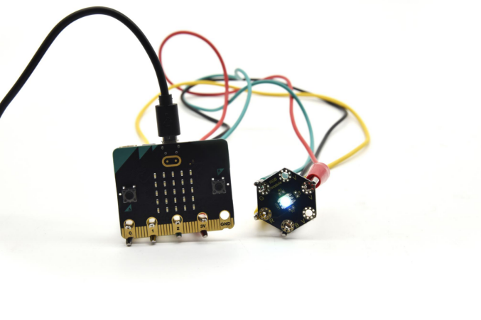
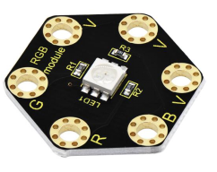
keyestudio 5050 RGB Module For BBC micro:bit
This module mainly contains a 5050 RGB LED, fully compatible with micro:bit control board. When using, connect the RGB module to micro:bit control board using Crocodile clip line.
There are total 6 rings on the module. Note that three V rings are connected. V ring for 3V; R G B ring is separately connected to signal pin (0 1 2) of micro:bit main board.
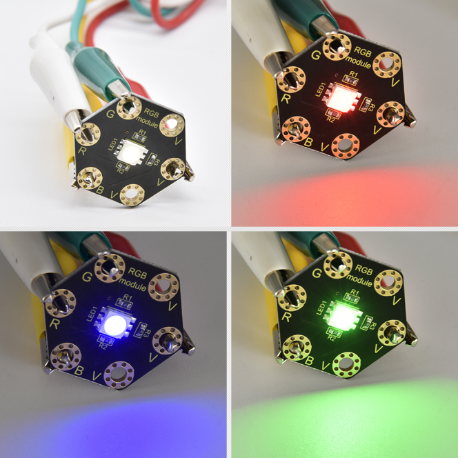
When three signal pins are LOW, this module gradually shows red, green and blue light.
2.Technical Parameters
Working voltage: DC 3.0-3.3V
Control mode: active LOW(common anode)
Dimensions: 31mm*27mm*3mm
Weight: 1.8g
Environmental attributes: ROHS
3.Components Required:
Micro:bit main board *1
keyestudio 5050 RGB Module for micro:bit *1
Alligator clip cable *4
USB cable *1
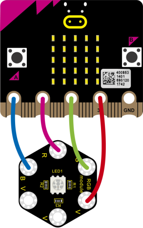
4.Connection Diagram
Connect the keyestudio 5050 RGB Module to micro:bit main board with 4 Alligator clip cables. Ring B to P0, R to P1, G to GND, V to 3V.
5.Coding
So now let’s move to coding. Let us see how to code the RGB LED to flash. Below are some steps to follow.
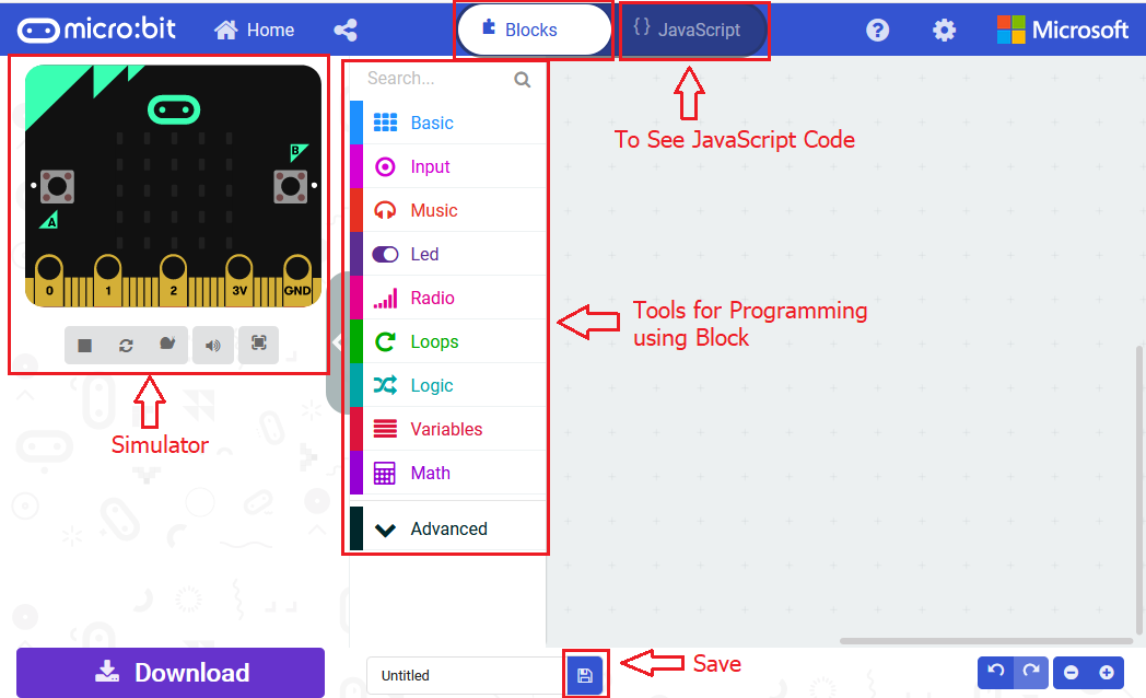
Open the https://makecode.micro:bit.org/#editor to write your code.
Microsoft MakeCode is actually a platform that allows us to code for a micro:bit, and also provides an interactive simulator where we can debug and run our code, and will be able to see what to expect out right there on the site.
Go to MakeCode and choose My Projects and click on New Projects.
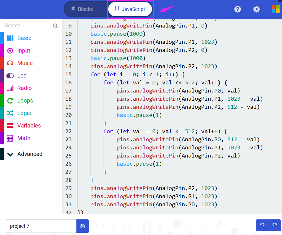
If you want to see the codes behind, then you can click on JavaScript and it will display JavaScript code there in IDE.
6.RGB LED Flashes
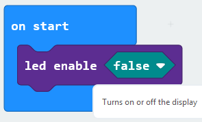
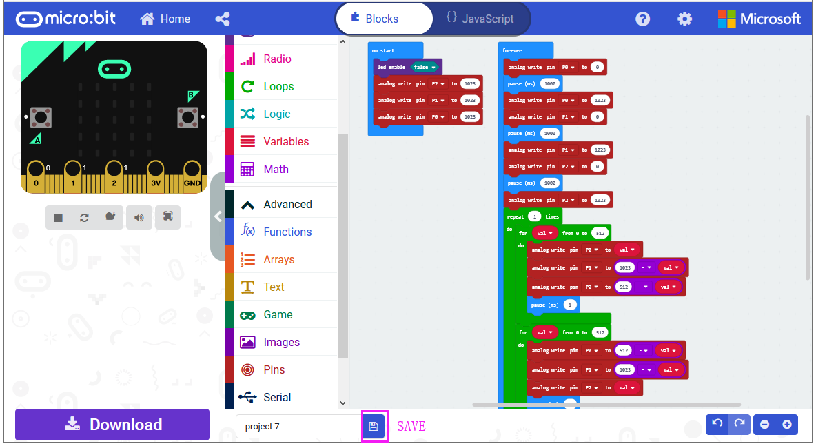
Let’s get started and code RGB LED to shine three colors. To do so, you just need to go to Basic and scroll down to see an on start block.
Now drag and drop, and go to Led and click more to drag out the block led enable(false) into on start block.
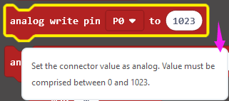
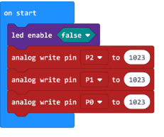
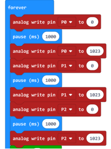
Go to the Pins, drag and drop the analog write pin(P0) to (1023) block into forever block. Duplicate this block twice, and change the pin to P1, P2.
Look at the connection diagram, we separately connect the Red,Green, Blue pin to P1, P2, P0. Connect the V pin to 3.3V.
So we first set all the pin value to 1023, which means input a HIGH level 3.3V (no voltage difference) to turn off all the LEDs;
And again go to Basic and drag the forever block beneath the on start block you just made.
We duplicate and drag the analog write pin(P0) to (1023) block into the forever block. Change the P0 value to 0, which means input a LOW level (0V)(with voltage difference) so as to lit the Blue LED.
Add a pause block in millisecond; and then duplicate the analog write pin(P0) to (1023) block several times.
We first turn on the Blue LED (P0) for 1 second then off, followed by turn Red LED (P1) on for 1 second then off; and turn Green LED (P2) on for 1 second then off.
Now let’s move on code the program we’ve written. Go to make the RGB led change in different brightness.
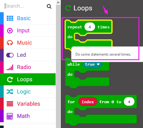
Go to Loops, drag and drop the repeat()times do() block into the block just made. Repeat 1 times.
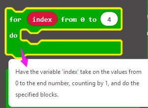
Then we drag the block for (index) from 0 to (4) do into the repeat()times do() block; and set to the variable val from 0 to 512.
After that, duplicate the analog write pin block three times; then call the Variables and Math block.
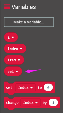
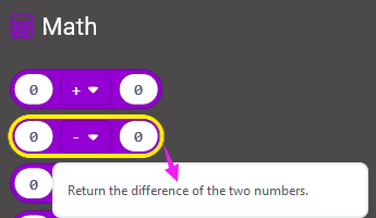
Using the variables adjust the RGB color-ratio to make the color change.
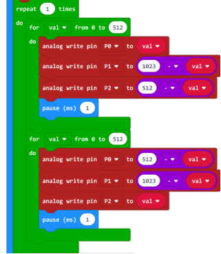
Finally we duplicate and set the analog write pin 2, 1, 0 value to 1023, which means input a HIGH level (no voltage difference) to turn off all the LEDs.
You can click on JavaScript and it will display JavaScript code there in IDE.
After completing the code, let’s move on to name and download the program we’ve written.

7.Test Code:
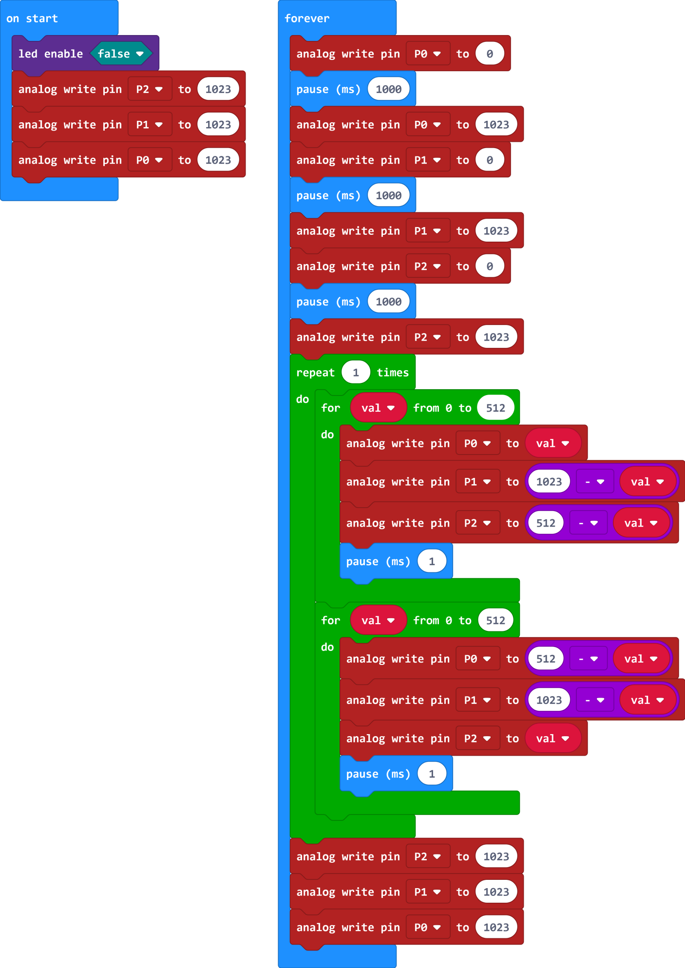
8.Result
Connect the micro:bit to your computer with a micro USB cable. You can right-click the micro:bit HEX file to send to your micro:bit main board.
Powered on, the RGB LED on the module will alternately flash red, blue and green light and make a slight change of brightness .