Project 16 Capacitive Touch Module
1.Overview
keyestudio Capacitive Touch Module For BBC micro:bit
This keyestudio capacitive touch module is fully compatible with micro:bit control board.
There are total 6 rings on the module. Note that two G rings, two V rings and two S rings are separately connected. G for ground; V for 3V; S for signal pin(0 1 2).
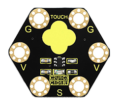
It mainly uses touch detection IC, which is a digital signal output device.
The touch detection IC is designed to replace the traditional button with a variable area key, featuring low power consumption and wide operating voltage.
When power on the module, it needs a stabilization time of about 0.5 sec. During this time period, do not touch the keypad. At this time, all functions are disabled, and self-calibration is always performed. No touching the key, the recalibration period is about 4.0sec.
Capacitive touch sensors are used in many devices such as laptop trackpads, digital audio players, computer displays, mobile phones, mobile devices, tablets and others.
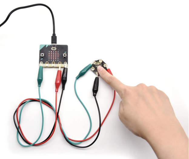
When using, connect the module to micro:bit control board using Crocodile clip line.
When touch the sensing area, input HIGH level signal to micro:bit signal end, LED on the module will turn on; or else, turn off.
2.Technical Parameters
Working voltage: DC 3.0-3.3V
Output Signal: Digital
Dimensions: 31mm*27mm*2.5mm
Weight: 1.7g
Environmental attributes: ROHS
3.Components Required
Micro:bit main board *1
Keyestudio Capacitive Touch Module for micro:bit *1
Alligator clip cable *3
USB cable *1
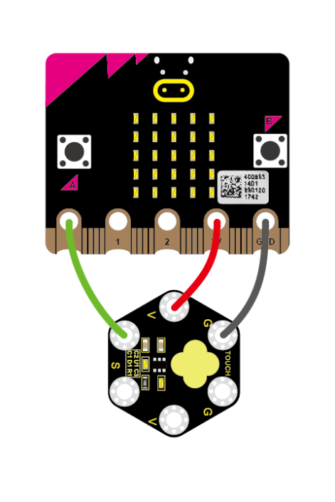
4.Connection Diagram
Connect the keyestudio Capacitive Touch Module to micro:bit main board with 3 Alligator clip cables. Ring S to P0, V to 3V, G to GND.
Connect the micro:bit to your computer with a micro USB cable.
5.Coding
So now let’s move to coding. Let us see how to code the microbit LED matrix to show icons with Capacitive Touch module. Below are some steps to follow.
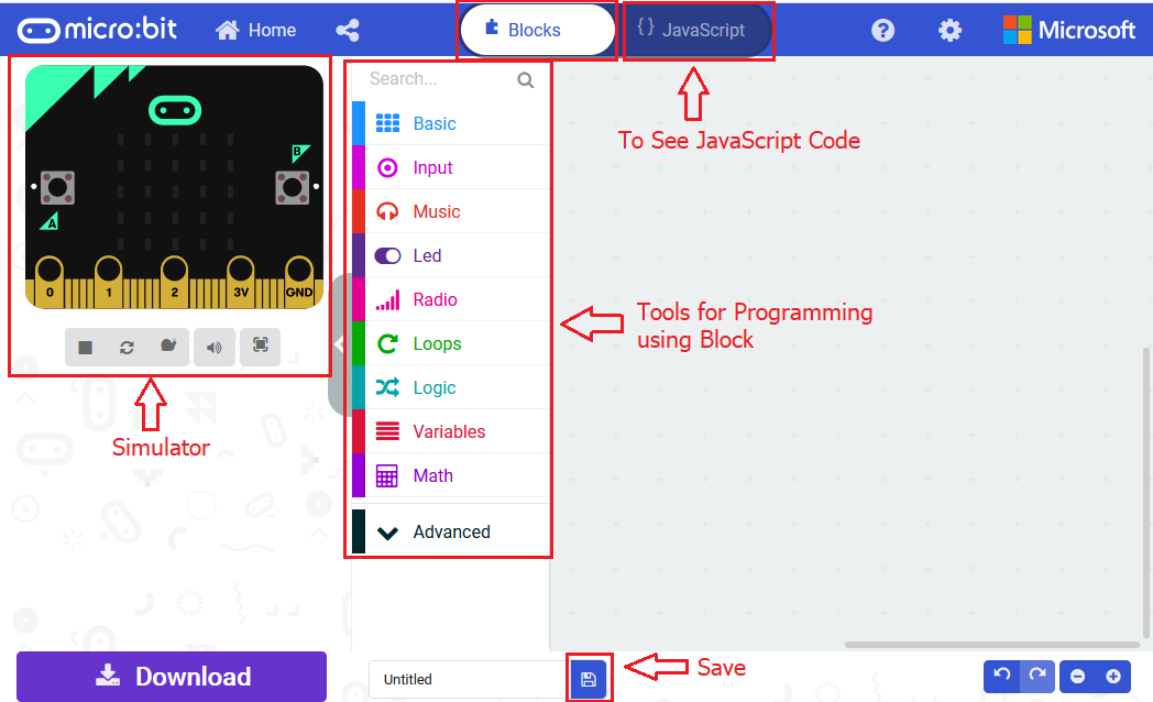
Open the https://makecode.micro:bit.org/#editor to write your code.
Microsoft MakeCode is actually a platform that allows us to code for a micro:bit, and also provides an interactive simulator where we can debug and run our code, and will be able to see what to expect out right there on the site.
Go to MakeCode and choose My Projects and click on New Projects.
If you want to see the codes behind, then you can click on JavaScript and it will display JavaScript code there in IDE.
6.Use Capacitive Touch to Control LED
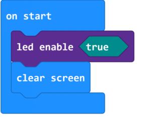
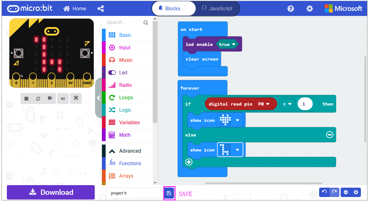
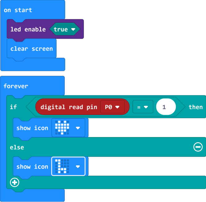
Let’s get started and show icons on micro:bit via Capacitive Touch control. To do so, you just need to go to Basic and scroll down to see an on start and clear screen block.
Now drag and drop, and go to Led and click more to drag out the block led enable(true) into on start block.
And again go to Basic and drag the forever block beneath the on start block you just made.
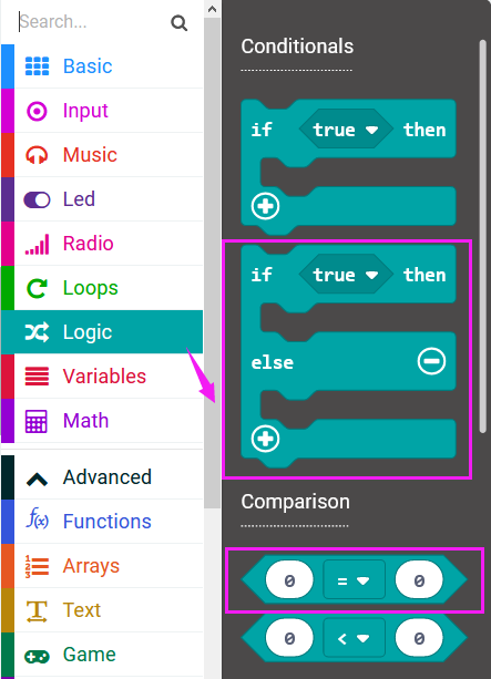
Now drag and drop, and go to Logic and search for **if (true) then…else…**block.
Drag this logic conditional block into forever block.
And add a comparison block to the logic conditional block.

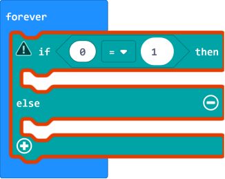
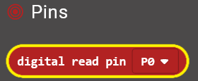
Go to the Pins, drag and drop the digital read pin(P0) block into **if (0)=(1) then…else…**block, replacing the “0” field.
Look back at the connection diagram, we connect the signal pin to P0. So we select the P0 in the code; and input 1, which means input a HIGH level to the pin so as to lit the LED.
And then again go to Basic and drag the show icon block beneath the logic block you just made. Otherwise show another icon.
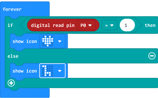
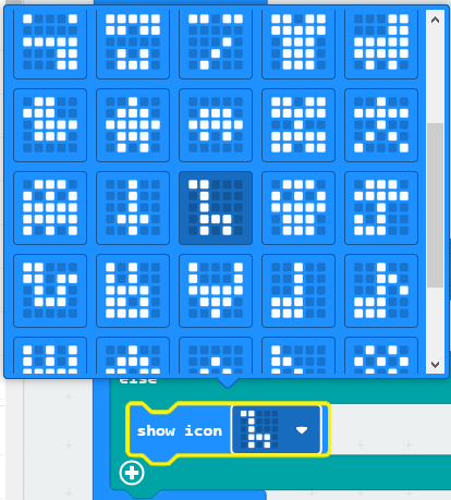
You can click the drop-down triangle to scroll down to choose the icon you want.
After completing the code, let’s move on to name and download the program we’ve written.
7.Test Code
8.Result
Connect the micro:bit to your computer with a micro USB cable. You can right-click the microbit HEX file to send to your micro:bit main board.

Touch the module’s sensing area, the micro:bit main board will show a heart shape icon. No touch, the LED matrix will show another icon.