4. Arduino Tutorial
4.1 Data download
Arduino information contains library files and project code ,please click to download for follow-up study.
Data download:Arduino Data
4.2 Software Download
When we get control board, we need to download Arduino IDE and driver firstly.
You could download Arduino IDE from the official website:https://www.arduino.cc/en/software.
There are various versions for Arduino,just download a suitable version for your system.
Windows:

You just need to click JUSTDOWNLOAD,then click the downloaded file to install it.
And when the ZIP file is downloaded,you can directly unzip and start it.

Mac:

4.3 Set Arduino IDE
Connecting the board to the computer.

4.4 Add Library
What are Libraries ?
Libraries are a collection of code that makes it easy for you to connect to a sensor,display, module, etc.
There are hundreds of additional libraries available on the Internet for download.
We will introduce the most simple way for you to add libraries .

4.5 Project
Project 1 Attitude Sensing Unit Test for Gesture Glove———>MPU6050
1.MPU6050
The MPU6050 is a 6-axis motion processor (combining a 3-axis gyroscope and a 3-axis accelerometer) integrated on a single chip. It can detect both static and dynamic motion states, including angular velocity and acceleration. The module is equipped with 16-bit ADCs, which simultaneously digitize data from all 6 axes, allowing the object’s angular velocity and acceleration to be measured accurately.
It also contains a temperature sensor to monitor the chip’s internal temperature during operation. Furthermore, it incorporates a DMP (Digital Motion Processor) to compute the object’s orientation (such as Euler angles or Quaternions) by processing raw data from the gyroscope and accelerometer, reducing the computational load on the host controller.

2.Circuit diagram
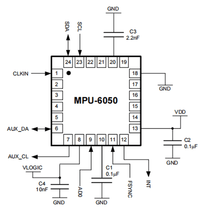
No. |
Name |
Description |
|---|---|---|
1 |
GND |
Negative pole interface (0V) |
2 |
VCC |
Positive pole interface (compatible with 3.3V and 5V) |
3 |
SDA |
I2C Data Line. It connects to MCU to transmit data. |
4 |
SCL |
I2C Clock Line. It connects to MCU to synchronize data transmission. |
5 |
XDA |
I2C Data Line. It connects to external sensors to transmit data. |
6 |
XCL |
I2C Clock Line. It connects to external sensors to synchronize data transmission. |
7 |
AD0 |
I2C sub-address. The address is 0x69 when the board is at a high level, while the address is 0x68 when at low. |
8 |
INT |
An external interrupt pin. It detects MPU6050 internal interrupt time. |
Operating voltage: 3.3V, 5V
Static current: 5μA
Rotating current: 3mA
Maximum rotation speed: 2000°/s
Acceleration scales: ±2g, ±4g, ±8g, ±16g
Temperature range: –10°C ~ +65°C
3.MPU6050 Data Acquisition
Note: Since both Bluetooth module communication and code uploads utilize the hardware serial port, you must disconnect the Bluetooth module before each code upload and reconnect it only after the upload completes. If the course does not require Bluetooth functionality, you may choose to leave the Bluetooth module disconnected.
Experiment 1 (Acquiring Raw MPU6050 Values)
#include <MPU6050.h>

MPU6050lib mpu;

int16_t accelCount[3];          // Store 16-bit signed output of acclerometer
int16_t gyroCount[3];           // Store 16-bit signed output of gyroscope
int16_t tempCount;              // Store the real internal chip temperature in degrees Celsius
float gyroBias[3] = {0, 0, 0};  // Correct gyroscope and acclerometer bias
float accelBias[3] = {0, 0, 0};
float SelfTest[6];              // Self-test value storing container

void setup()
{
  Wire.begin();
  Serial.begin(9600);
  // Read the WHO_AM_I register, this is a good test of communication
  // Read WHO_AM_I register for MPU-6050
  uint8_t c = mpu.readByte(MPU6050_ADDRESS, WHO_AM_I_MPU6050);
  Serial.print("I AM ");
  Serial.print(c, HEX);
  //Set the minimum scale if the device is in self-test
  // Possible gyro scales (and their register bit settings) are:
  // 250 DPS (0x00), 500 DPS (0x01), 1000 DPS (0x10), and 2000 DPS  (0x11).
  // Possible accelerometer scales (and their register bit settings) are:
  // 2 Gs (0x00), 4 Gs (0x01), 8 Gs (0x10), and 16 Gs  (0x11).
  mpu.settings(AFS_8G, GFS_250DPS);
  // version WHO_AM_I should always be 0x68 //MPU6050  address 1: 0x68, address 2: 0x98
  if (c == 0x68 || c == 0x98)
  {
    Serial.println("MPU6050 is online...");
    // Start by performing self test
    mpu.MPU6050SelfTest(SelfTest);

    if (SelfTest[0] < 1.0f && SelfTest[1] < 1.0f && SelfTest[2] < 1.0f && SelfTest[3] < 1.0f && SelfTest[4] < 1.0f
    && SelfTest[5] < 1.0f)
    {
      Serial.println("Pass Selftest!");
      // Calibrate gyro and accelerometers, load biases in bias registers
      mpu.calibrateMPU6050(gyroBias, accelBias);
      mpu.settings(AFS_2G, GFS_250DPS);
      mpu.initMPU6050();
      // Initialize device for active mode read of acclerometer, gyroscope, and temperature
      Serial.println("MPU6050 initialized for active data mode....");
    }
    else
    {
      Serial.print("Could not connect to MPU6050: 0x");
      Serial.println(c, HEX);
      // Loop forever if communication doesn't happen
      while (1) ;
    }
  }
}

void loop()
{
  // If data ready bit set, all data registers have new data
  // check if data ready interrupt
  if (mpu.readByte(MPU6050_ADDRESS, INT_STATUS) & 0x01)
  {
    // Read the x/y/z adc values
    mpu.readAccelData(accelCount);
    // Read the x/y/z adc values
    mpu.readGyroData(gyroCount);
    Serial.println("--------");
    Serial.print("Accel X:");
    Serial.println(accelCount[0]);
    Serial.print("Accel Y:");
    Serial.println(accelCount[1]);
    Serial.print("Accel Z:");
    Serial.println(accelCount[2]);
    Serial.println("--------");
    Serial.print("Gyro X:");
    Serial.println(gyroCount[0]);
    Serial.print("Gyro Y:");
    Serial.println(gyroCount[1]);
    Serial.print("Gyro Z:");
    Serial.println(gyroCount[2]);
    Serial.println("--------");
    // Read the x/y/z adc values
    tempCount = mpu.readTempData();
    // Temperature in degrees Centigrade
    Serial.print("Initial TEMP values:");
    Serial.println(tempCount);
    Serial.println("--------");
    delay(500);
  }
}
Place the expansion board smoothly, press and hold the reset button. The more balanced the MPU6050 is, the more accurate the data it acquired will be.
When you open the serial monitor, you will see three repeated data blocks, with the following meanings:
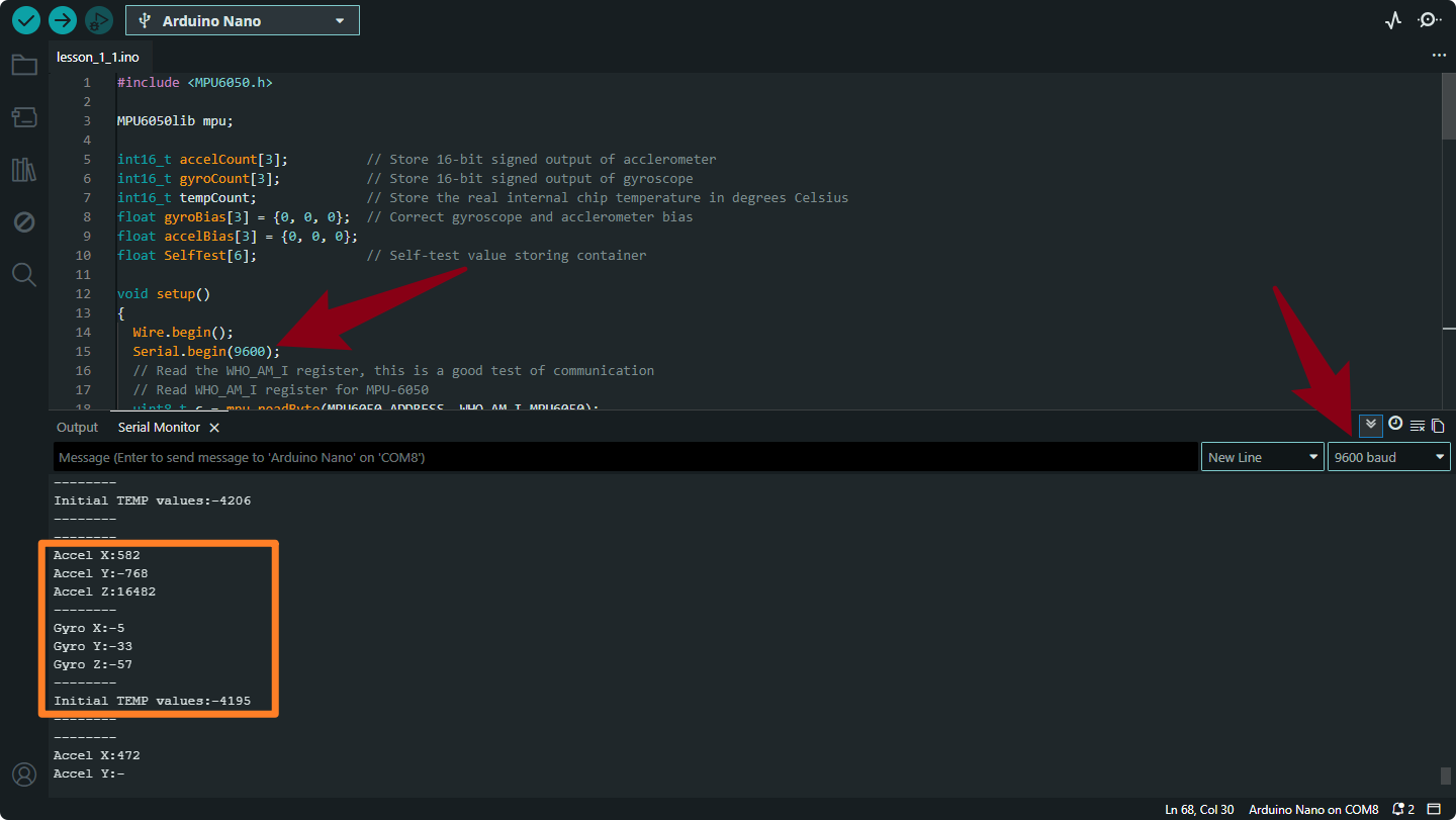
Accel X, Accel Y, Accel Z
Meaning: Represents Linear Acceleration (including gravity) detected along the X, Y, and Z axes.
Unit: Raw LSB (Least Significant Bit) counts.
Note: Since
AFS_2Gis set in your setup, a value of approx 16,384 equals 1 g (gravity). If the sensor is flat on a table, Z should be near 16,384 (or -16,384 depending on orientation), while X and Y should be near 0.
Gyro X, Gyro Y, Gyro Z
Meaning: Represents Angular Velocity (Rotational Speed). It measures how fast the sensor is rotating around the X, Y, and Z axes.
Unit: Raw LSB counts.
Note: Since GFS_250DPS is set, a value of 131 equals 1 degree per second. If the sensor is stationary, these values should be very close to 0.
Initial TEMP values
Meaning: Represents the Internal Die Temperature of the MPU6050 chip.
Unit: Raw LSB counts.
Note: This is not degrees Celsius yet. You must apply a formula to convert it (usually: \(\text{Temp}_{C} = \frac{\text{RawValue}}{340.0} + 36.53\)).
Experiment 2 (MPU6050 Temperature Acquisition and Conversion)
#include <MPU6050.h>

MPU6050lib mpu;

int16_t tempCount;              // Store the real internal chip temperature in degrees Celsius
float temperature;              // Store the actual temperature in degrees Celsius
float gyroBias[3] = {0, 0, 0};  // Correct gyroscope and acclerometer bias
float accelBias[3] = {0, 0, 0};
float SelfTest[6];              // Self-test value storing container

void setup()
{
  Wire.begin();
  Serial.begin(9600);
  // Read the WHO_AM_I register, this is a good test of communication
  // Read WHO_AM_I register for MPU-6050
  uint8_t c = mpu.readByte(MPU6050_ADDRESS, WHO_AM_I_MPU6050);
  Serial.print("I AM ");
  Serial.print(c, HEX);
  //Set the minimum scale if the device is in self-test
      // Possible gyro scales (and their register bit settings) are:
      // 250 DPS (0x00), 500 DPS (0x01), 1000 DPS (0x10), and 2000 DPS  (0x11).
      // Possible accelerometer scales (and their register bit settings) are:
      // 2 Gs (0x00), 4 Gs (0x01), 8 Gs (0x10), and 16 Gs  (0x11).
  mpu.settings(AFS_8G, GFS_250DPS);
  // version WHO_AM_I should always be 0x68 //MPU6050  address 1: 0x68, address 2: 0x98
  if (c == 0x68 || c == 0x98) {
    Serial.println("MPU6050 is online...");
    // Start by performing self test
    mpu.MPU6050SelfTest(SelfTest);
    if (SelfTest[0] < 1.0f && SelfTest[1] < 1.0f && SelfTest[2] < 1.0f && SelfTest[3] < 1.0f && SelfTest[4] < 1.0f
    && SelfTest[5] < 1.0f)
    {
      Serial.println("Pass Selftest!");
      // Calibrate gyro and accelerometers, load biases in bias registers
      mpu.calibrateMPU6050(gyroBias, accelBias);
      mpu.settings(AFS_2G, GFS_250DPS);
      mpu.initMPU6050();
      // Initialize device for active mode read of acclerometer, gyroscope, and temperature
      Serial.println("MPU6050 initialized for active data mode....");
    }
    else{
      Serial.print("Could not connect to MPU6050: 0x");
      Serial.println(c, HEX);
      // Loop forever if communication doesn't happen
      while (1) ;
    }
  }
}

void loop()
{
  // If data ready bit set, all data registers have new data
  // check if data ready interrupt
  if (mpu.readByte(MPU6050_ADDRESS, INT_STATUS) & 0x01)
  {
    tempCount = mpu.readTempData();  // Read the x/y/z adc values
    temperature = ((float) tempCount) / 340. + 36.53; // Temperature in degrees Centigrade
  }
  Serial.println("--------");
  // Temperature in degrees Centigrade
  Serial.print("TEMP values:");
  Serial.println(temperature);
  Serial.println("--------");
  delay(500);
}
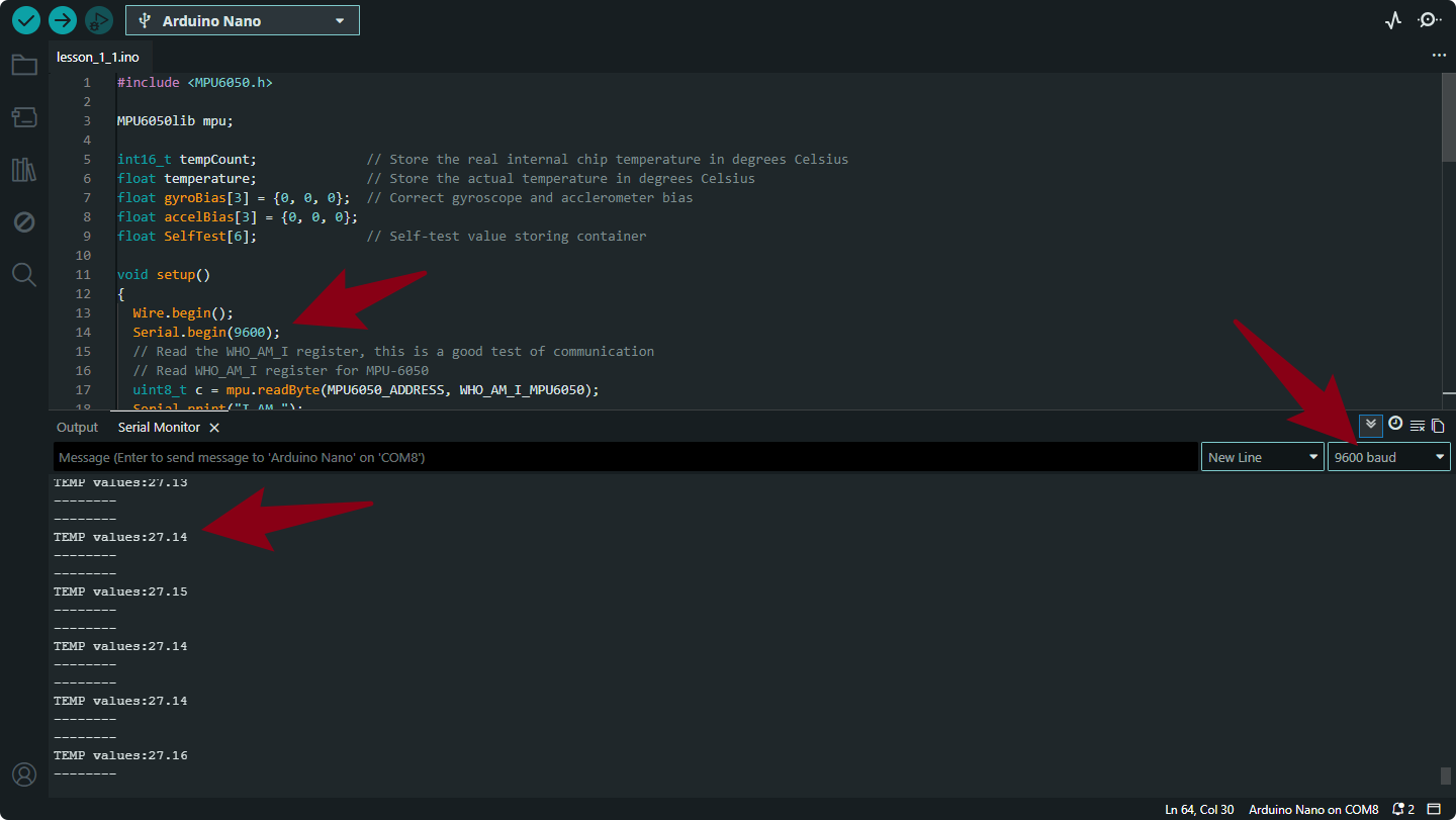
Output Data Explanation
This code specifically measures the Internal Temperature of the MPU6050 chip and converts it into a human-readable format.
TEMP values: [Number]
Meaning: This represents the actual temperature of the sensor chip in Degrees Celsius (°C).
Difference from previous code: In the previous code, you saw a raw integer (e.g.,
1600). In this code, the linetemperature = ((float) tempCount) / 340. + 36.53;converts that raw number into a real temperature (e.g.,26.50).Note: This is the temperature of the silicon die inside the chip, not necessarily the exact room air temperature (though it is usually close).
Project 2 MPU6050 Attitude Fusion Solution (Madgwick Filter)
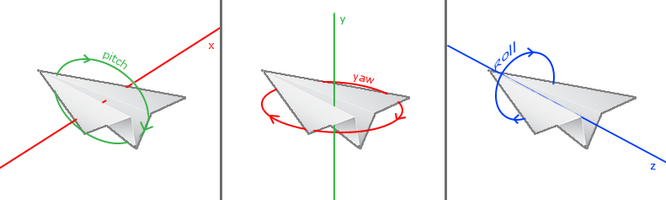
1.Introduction to Attitude
Attitude refers to the orientation of an object in 3D space. The MPU6050 measures this using three angles known as Euler Angles:
Roll: Rotation around the X-axis (tilting left/right).
Pitch: Rotation around the Y-axis (tilting forward/backward).
Yaw: Rotation around the Z-axis (turning left/right).
Why use Quaternions?
While Euler angles are easy to understand, they suffer from Gimbal Lock (loss of one degree of freedom at certain angles). To solve this, we use Quaternions—a mathematical representation using four numbers (\(q_0, q_1, q_2, q_3\)) that simplify calculations and ensure smooth rotation tracking for drones and robots.
2. The Attitude Acquisition Process
The process follows a specific workflow to ensure raw sensor “noise” is filtered into clean data.
Step 1: Convert Accelerometer Data
Raw data from the ADC must be converted into G-force (\(g\)).
Formula: \(Acceleration = \frac{Original Value}{Resolution}\)
mpu.readAccelData(accelCount);
aRes = mpu.getAres(); // Get LSB/g resolution
ax = (float)accelCount[0] * aRes;
ay = (float)accelCount[1] * aRes;
az = (float)accelCount[2] * aRes;
Step 2: Convert Gyroscope Data
Convert raw angular speed into Degrees per Second (\(°/s\)).
Formula: \(Angular Speed = \frac{Original Value}{Resolution}\)
mpu.readGyroData(gyroCount);
gRes = mpu.getGres(); // Get LSB/(°/s) resolution
gyrox = (float)gyroCount[0] * gRes;
gyroy = (float)gyroCount[1] * gRes;
gyroz = (float)gyroCount[2] * gRes;
Step 3: Calculate Integration Interval
The algorithm needs to know exactly how much time has passed between updates (deltat) to integrate the movement accurately.
Now = micros();
deltat = ((Now - lastUpdate) / 1000000.0f); // Convert microseconds to seconds
lastUpdate = Now;
Step 4: Madgwick Quaternion Update
Before fusion, we convert gyroscope data to Radians because the math requires circular measurement (\(Radians = Degrees \times \frac{\pi}{180}\)).
// Convert to Radians
gyrox *= (PI / 180.0f);
gyroy *= (PI / 180.0f);
gyroz *= (PI / 180.0f);

// Update Quaternion using Madgwick Filter
MadgwickQuaternionUpdate(ax, ay, az, gyrox, gyroy, gyroz);
Inside the Filter:
Normalize the accelerometer vector.
Compute the Gradient via the Jacobian matrix to find the direction of the error.
Correct Gyro Bias to remove “Null Shift” (drift).
Integrate the rate of change to find the new Quaternion state.
Converting Quaternions to Euler Angles
Finally, we convert the abstract Quaternions back into human-readable degrees.
// Mathematical Conversion
pitch = -asin(2.0f * (q[1] * q[3] - q[0] * q[2]));
roll  = atan2(2.0f * (q[0] * q[1] + q[2] * q[3]), q[0] * q[0] - q[1] * q[1] - q[2] * q[2] + q[3] * q[3]);

// Convert Radians back to Degrees for display
pitch *= 180.0f / PI;
roll  *= 180.0f / PI;
3.code
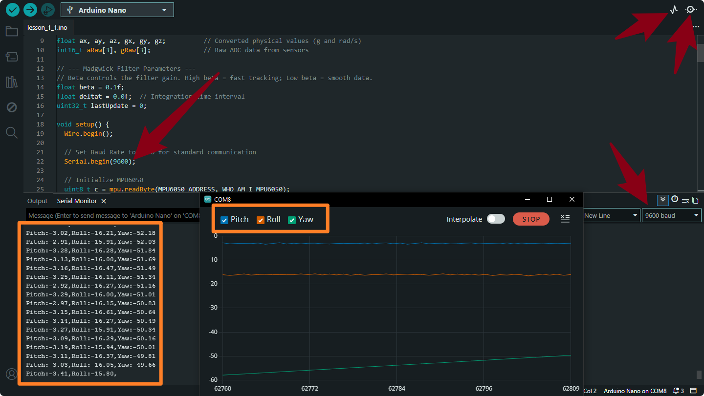
Based on the above principles, we can write the following code. After uploading the code, we open the serial monitor and serial plotter respectively. By changing the glove’s posture, we can obtain real-time posture data from the glove.
#include "Wire.h"
#include "MPU6050.h"

MPU6050lib mpu;

// --- Core Attitude Variables ---
float q[4] = {1.0f, 0.0f, 0.0f, 0.0f}; // Quaternion buffer [qw, qx, qy, qz]
float pitch, roll, yaw;                // Calculated Euler angles (Degrees)
float ax, ay, az, gx, gy, gz;          // Converted physical values (g and rad/s)
int16_t aRaw[3], gRaw[3];              // Raw ADC data from sensors

// --- Madgwick Filter Parameters ---
// Beta controls the filter gain. High beta = fast tracking; Low beta = smooth data.
float beta = 0.1f;
float deltat = 0.0f;  // Integration time interval
uint32_t lastUpdate = 0;

void setup() {
  Wire.begin();

  // Set Baud Rate to 9600 for standard communication
  Serial.begin(9600);

  // Initialize MPU6050
  uint8_t c = mpu.readByte(MPU6050_ADDRESS, WHO_AM_I_MPU6050);
  if (c == 0x68) {
    Serial.println(F("MPU6050 Online. Starting Calibration..."));

    float gBias[3], aBias[3];
    // Keep the sensor flat and still during calibration
    mpu.calibrateMPU6050(gBias, aBias);
    mpu.initMPU6050();

    Serial.println(F("Calibration Complete. Format: Pitch, Roll, Yaw"));
  } else {
    Serial.print(F("Connection Error: 0x"));
    Serial.println(c, HEX);
    while (1); // Halt if sensor not found
  }
}

void loop() {
  // 1. Check if Data Ready interrupt is set
  if (mpu.readByte(MPU6050_ADDRESS, INT_STATUS) & 0x01) {

    // Read Accelerometer and convert to g
    mpu.readAccelData(aRaw);
    float aRes = mpu.getAres();
    ax = (float)aRaw[0] * aRes;
    ay = (float)aRaw[1] * aRes;
    az = (float)aRaw[2] * aRes;

    // Read Gyroscope and convert to Radians per Second
    mpu.readGyroData(gRaw);
    float gRes = mpu.getGres();
    gx = (float)gRaw[0] * gRes * PI / 180.0f;
    gy = (float)gRaw[1] * gRes * PI / 180.0f;
    gz = (float)gRaw[2] * gRes * PI / 180.0f;

    // 2. Update Integration Time (dt)
    uint32_t now = micros();
    deltat = (now - lastUpdate) / 1000000.0f;
    lastUpdate = now;

    // 3. Update Quaternion using Madgwick algorithm
    MadgwickQuaternionUpdate(ax, ay, az, gx, gy, gz);

    // 4. Convert Quaternion to Euler Angles (Tait-Bryan convention)
    // Yaw: Turning left/right (drift-prone without magnetometer)
    // Pitch: Forward/Backward tilt
    // Roll: Side-to-side tilt
    yaw   = atan2(2.0f * (q[1] * q[2] + q[0] * q[3]), q[0] * q[0] + q[1] * q[1] - q[2] * q[2] - q[3] * q[3]);
    pitch = -asin(2.0f * (q[1] * q[3] - q[0] * q[2]));
    roll  = atan2(2.0f * (q[0] * q[1] + q[2] * q[3]), q[0] * q[0] - q[1] * q[1] - q[2] * q[2] + q[3] * q[3]);

    // 5. Convert Radians to Degrees
    pitch *= 180.0f / PI;
    roll  *= 180.0f / PI;
    yaw   *= 180.0f / PI;

    // 6. Print data for Serial Monitor/Plotter
    Serial.print("Pitch:"); Serial.print(pitch);
    Serial.print(",");
    Serial.print("Roll:");  Serial.print(roll);
    Serial.print(",");
    Serial.print("Yaw:");   Serial.println(yaw);
  }

  // Control the loop frequency (~100Hz)
  delay(10);
}

// --- Madgwick Filter Implementation ---
// Efficiently fuses accelerometer and gyroscope data to produce stable attitude.
void MadgwickQuaternionUpdate(float ax, float ay, float az, float gx, float gy, float gz) {
  float q1 = q[0], q2 = q[1], q3 = q[2], q4 = q[3];
  float norm;
  float f1, f2, f3;
  float J_11or24, J_12or23, J_13or22, J_14or21, J_32, J_33;
  float qDot1, qDot2, qDot3, qDot4;
  float hatDot1, hatDot2, hatDot3, hatDot4;

  // Normalize accelerometer measurement
  norm = sqrt(ax * ax + ay * ay + az * az);
  if (norm == 0.0f) return;
  norm = 1.0f / norm;
  ax *= norm; ay *= norm; az *= norm;

  // Pre-calculate common variables
  float _2q1 = 2.0f * q1, _2q2 = 2.0f * q2, _2q3 = 2.0f * q3, _2q4 = 2.0f * q4;

  // Compute objective function and Jacobian
  f1 = _2q2 * q4 - _2q1 * q3 - ax;
  f2 = _2q1 * q2 + _2q3 * q4 - ay;
  f3 = 1.0f - _2q2 * q2 - _2q3 * q3 - az;
  J_11or24 = _2q3; J_12or23 = _2q4; J_13or22 = _2q1; J_14or21 = _2q2;
  J_32 = 2.0f * J_14or21; J_33 = 2.0f * J_11or24;

  // Compute the gradient (matrix multiplication)
  hatDot1 = J_14or21 * f2 - J_11or24 * f1;
  hatDot2 = J_12or23 * f1 + J_13or22 * f2 - J_32 * f3;
  hatDot3 = J_12or23 * f2 - J_33 * f3 - J_13or22 * f1;
  hatDot4 = J_14or21 * f1 + J_11or24 * f2;

  // Normalize the gradient
  norm = 1.0f / sqrt(hatDot1 * hatDot1 + hatDot2 * hatDot2 + hatDot3 * hatDot3 + hatDot4 * hatDot4);
  hatDot1 *= norm; hatDot2 *= norm; hatDot3 *= norm; hatDot4 *= norm;

  // Compute quaternion derivative (rate of change)
  qDot1 = 0.5f * (-q2 * gx - q3 * gy - q4 * gz);
  qDot2 = 0.5f * (q1 * gx + q3 * gz - q4 * gy);
  qDot3 = 0.5f * (q1 * gy - q2 * gz + q4 * gx);
  qDot4 = 0.5f * (q1 * gz + q2 * gy - q3 * gx);

  // Integrate to find next attitude state
  q1 += (qDot1 - (beta * hatDot1)) * deltat;
  q2 += (qDot2 - (beta * hatDot2)) * deltat;
  q3 += (qDot3 - (beta * hatDot3)) * deltat;
  q4 += (qDot4 - (beta * hatDot4)) * deltat;

  // Normalize final quaternion
  norm = 1.0f / sqrt(q1 * q1 + q2 * q2 + q3 * q3 + q4 * q4);
  q[0] = q1 * norm; q[1] = q2 * norm; q[2] = q3 * norm; q[3] = q4 * norm;
}
Instructions for Use:
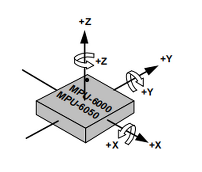
Coordinate System: Understand the axis layout of the MPU6050 to correctly interpret Pitch and Roll.
Serial Monitor: Open the Arduino Serial Monitor and set the baud rate to 9600. You will see the numeric values.
Serial Plotter: For a better experience, go to Tools > Serial Plotter. You will see smooth, colorful lines representing your movement in real-time.
Calibration: Ensure the sensor is on a flat, stable surface when you power it on or reset it, so the calibration can correctly remove the sensor bias.
Project 3 Bluetooth Data Transmission
1.Hardware Overview
Master Bluetooth module (straight-pin version):

The DX-BT24 master Bluetooth module uses the Dialog 14531 chip, complies with the BLE 5.1 protocol, and provides transparent wireless transmission via UART.
Default serial settings: 9600 bps / 8 data bits / no parity / 1 stop bit.
Key features
Flexible baud-rate and name configuration
Ultra-low power: 2 µA
Master/slave LOS range: 20 m / 90 m
Up to 115 200 bps transparent throughput
2.Master-Slave Bluetooth Module Pairing
Method One:BT24 One-Click Master–Slave Pairing (No AT Commands)
This method requires no AT commands—the first pairing and bind information are completed solely with the on-board buttons.
(1)Procedure
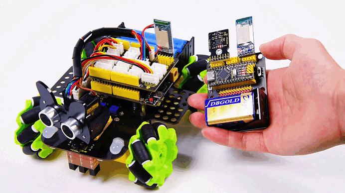
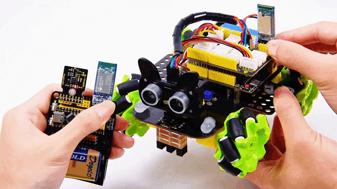
(The gesture-control kit includes a BT24 master module. A BT24 slave module—typically mounted on a smart car—must be purchased separately. The demo below uses the keyestudio mecanum-wheel car.)
Prepare
Both BT24 modules (master and slave) are powered correctly and not connected to other devices.
After power-up, both indicator LEDs blink, meaning “not connected”.
Press Buttons Simultaneously
Long-press the buttons on both modules for about 3–5 s until the LEDs on both sides change from blinking to solid ON
Blinking → searching/pairing
Solid ON → paired and connected
Pairing Complete
Release the buttons. A steady LED indicates that the transparent link is established and will auto-reconnect after power loss.

(2)Status & Indicator LED
LED State |
Module Status |
Action |
|---|---|---|
Blinking |
Not connected / waiting to pair |
No action needed, or long-press again to enter pairing |
Solid ON |
Connected / transparent link open |
Ready to send & receive data |
Blinking (after short press) |
Clear binding |
Short-press once to erase pairing info |
To pair with a new device: short-press the buttons on master and slave → LEDs blink → repeat steps 3.1.
Method 2: (Using Your Own USB-to-TTL Module)
Of course, if you have a USB-to-TTL module, refer to Method Two—you only need to manually pair once, and subsequent Bluetooth master-slave modules will achieve automatic pairing.
1.Connect the Bluetooth module to the UAB-to-TTL module as follows:
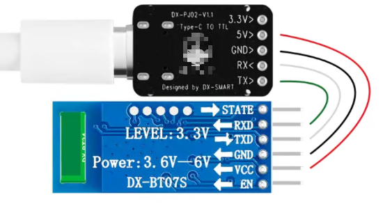
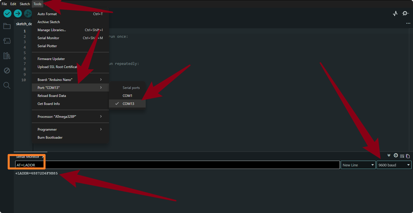
2.Connect the USB-to-TTL module to your computer. Open the Arduino Serial Monitor, select the port for the USB-to-TTL module, set the baud rate to 9600, send the command “AT+LADDR”, and record the received value.
3.Remove the Bluetooth slave module from the USB-to-TTL converter. Connect the Bluetooth master module to the USB-to-TTL converter using the same method. Send the command AT+BIND
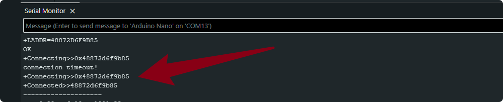
4.After successful connection, attach the Bluetooth master module to the glove and connect it to the cart. Once both are powered on, the two Bluetooth devices will automatically pair. No further manual pairing is required.
3.Arduino Sending Example

Upload the following code to the glove’s mainboard. Once the upload is complete, insert the Bluetooth master module into the glove’s expansion board.
void setup()
{
  Serial.begin(9600);// Initialize the serial port, and set the baud rate to 9600
}

void loop()
{
  Serial.println("A");
  delay(500);
  Serial.println("B");
  delay(500);
}
After uploading the code, open the serial monitor for both the Bluetooth master module (glove, left side in the image below) and the Bluetooth slave module (provided by the user, right side in the image below). You can observe the transmitted and received data. Of course, if you don’t have a slave module, you can just monitor the master module.
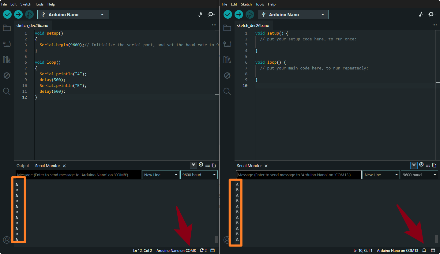
You should see the strings “A” and “B” alternating every 0.5 s.This confirms that the master’s data is transparently transmitted to the slave.
You have now completed data transmission from the BT24 master to the slave and can extend this approach to more complex wireless communication scenarios.
Project 4 Gesture Detection
By mounting an MPU6050 on the glove we can read the Roll and Pitch angles in real time and output the corresponding gestures through the serial port, paving the way for later Bluetooth transmission or mecanum-car control.
1.Attitude-Angle Overview
With only an MPU6050 on the glove, the Yaw (heading) angle drifts, so we read only Roll and Pitch.
For complete three-axis angles, add a magnetometer for calibration.
Roll (Y-axis)
Fingers pointing forward; rotate the hand left/right around the palm.
Angle |
Gesture |
|---|---|
0 ° |
Hand level |
–180 ° |
Fully rolled left |
+180 ° |
Fully rolled right |

Pitch (X-axis)
Fingers pointing forward; raise/lower the hand around the palm.
Angle |
Gesture |
|---|---|
0 ° |
Hand level |
–180 ° |
Hand raised |
+180 ° |
Hand pressed down |

2.Example Gesture Ranges
When the angles fall into the ranges below, you can treat them as the corresponding gestures (feel free to adjust):
Level: X and Y both –10 ° ~ 10 °
Roll-left: Y axis –20 ° ~ –90 °
Roll-right: Y axis 20 ° ~ 90 °
Raise-up: X axis 20 ° ~ 90 °
Press-down: X axis –20 ° ~ –90 °
Keep Bluetooth disconnected while uploading code; after flashing, open the Serial Monitor to view real-time angles and gesture text.
3.Code
#include "MPU6050.h"
MPU6050lib mpu;

float aRes, gRes;        // scale resolutions per LSB for the sensors
int16_t accelCount[3];      // Stores the 16-bit signed accelerometer sensor output
int16_t gyroCount[3];      // Stores the 16-bit signed gyro sensor output
float ax, ay, az;        // Stores the real accel value in g's
float gyrox, gyroy, gyroz;    // Stores the real gyro value in degrees per seconds
float gyroBias[3] = {0, 0, 0};
float accelBias[3] = {0, 0, 0}; // Bias corrections for gyro and accelerometer
int16_t tempCount;        // Stores the real internal chip temperature in degrees Celsius
float temperature;
float SelfTest[6];
float q[4] = {1.0f, 0.0f, 0.0f, 0.0f};// vector to hold quaternion
float pitch, yaw, roll;

// parameters for 6 DoF sensor fusion calculations
float GyroMeasError = PI * (40.0f / 180.0f);    //gyroscope measurement error in rads/s (start at 60 deg/s), then reduce after ~10 s to 3
float beta = sqrt(3.0f / 4.0f) * GyroMeasError;  // compute beta(β)
float GyroMeasDrift = PI * (2.0f / 180.0f);    // gyroscope measurement drift in rad/s/s (start at 0.0 deg/s/s)
float zeta = sqrt(3.0f / 4.0f) * GyroMeasDrift;  // compute zeta, the other free parameter in the Madgwick scheme usually set to a small or zero value
float deltat = 0.0f;                // integration interval for both filter schemes
uint32_t lastUpdate = 0, firstUpdate = 0;     // used to calculate integration interval
uint32_t Now = 0;                 // used to calculate integration interval


void setup()
{
  Wire.begin();
  Serial.begin(9600);


 // Read the WHO_AM_I register, this is a good test of communication

 uint8_t c = mpu.readByte(MPU6050_ADDRESS, WHO_AM_I_MPU6050); // Read WHO_AM_I register for MPU-6050

 Serial.print("I AM ");

 Serial.println(c, HEX);


 mpu.settings(AFS_8G, GFS_250DPS);

 if (c == 0x68) //WHO_AM_I should always be 0x68

 {

  Serial.println("MPU6050 is online...");

  // Start by performing self test and reporting values

  mpu.MPU6050SelfTest(SelfTest);

  Serial.print("x-axis self test: acceleration trim within : "); Serial.print(SelfTest[0],1); Serial.println("% of factory value");

  Serial.print("y-axis self test: acceleration trim within : "); Serial.print(SelfTest[1],1); Serial.println("% of factory value");

  Serial.print("z-axis self test: acceleration trim within : "); Serial.print(SelfTest[2],1); Serial.println("% of factory value");

  Serial.print("x-axis self test: gyration trim within : "); Serial.print(SelfTest[3],1); Serial.println("% of factory value");

  Serial.print("y-axis self test: gyration trim within : "); Serial.print(SelfTest[4],1); Serial.println("% of factory value");

  Serial.print("z-axis self test: gyration trim within : "); Serial.print(SelfTest[5],1); Serial.println("% of factory value");


  if (SelfTest[0] < 1.0f && SelfTest[1] < 1.0f && SelfTest[2] < 1.0f && SelfTest[3] < 1.0f && SelfTest[4] < 1.0f && SelfTest[5] < 1.0f) {

   Serial.println("Pass Selftest!");

   // Calibrate gyro and accelerometers, load biases in bias registers

   mpu.calibrateMPU6050(gyroBias, accelBias);

   Serial.println("MPU6050 bias");

   Serial.println(" x\t  y\t  z  ");

   Serial.print((int)(1000 * accelBias[0])); Serial.print('\t');

   Serial.print((int)(1000 * accelBias[1])); Serial.print('\t');

   Serial.print((int)(1000 * accelBias[2]));

   Serial.println(" mg");


   Serial.print(gyroBias[0], 1); Serial.print('\t');

   Serial.print(gyroBias[1], 1); Serial.print('\t');

   Serial.print(gyroBias[2], 1);

   Serial.println(" o/s");


   mpu.settings(AFS_2G, GFS_250DPS);

   mpu.initMPU6050();

   // Initialize device for active mode read of accelerometer , gyroscope, and temperature

   Serial.println("MPU6050 initialized for active data mode....");

  }

 }

 else

 {

  Serial.print("Could not connect to MPU6050: 0x");

  Serial.println(c, HEX);

  while(1); // Loop forever if communication doesn't happen

 }

}


void loop()

{

 // If data ready bit set, all data registers have new data

 if (mpu.readByte(MPU6050_ADDRESS, INT_STATUS) & 0x01) { // check if data ready interrupt

  mpu.readAccelData(accelCount);   // Read the x/y/z adc values

  aRes = mpu.getAres();       // Acquire the converted value


  // Now we'll calculate the accleration value into actual g's

  ax = (float)accelCount[0] * aRes; // get actual g value, this depends on scale being set

  ay = (float)accelCount[1] * aRes;

  az = (float)accelCount[2] * aRes;


  mpu.readGyroData(gyroCount);    // Read the x/y/z adc values

  gRes = mpu.getGres();       // Acquire the converted value


  // Calculate the gyro value into actual degrees per second

  gyrox = (float)gyroCount[0] * gRes; // get actual gyro value, this depends on scale being set

  gyroy = (float)gyroCount[1] * gRes;

  gyroz = (float)gyroCount[2] * gRes;


  tempCount = mpu.readTempData(); // Read the x/y/z adc values

  temperature = ((float) tempCount) / 340. + 36.53; // Temperature in degrees Centigrade

 }

 // Acquire the current time of the system in ms

 Now = micros();

 // set integration time by time elapsed since last filter update

 deltat = ((Now - lastUpdate) / 1000000.0f);

 lastUpdate = Now;

 if(lastUpdate - firstUpdate > 10000000uL) {

  beta = 0.041; // decrease filter gain after stabilized

  zeta = 0.015; // increase gyro bias drift gain after stabilized

 }

 // Convert the gyroscope data to radians

 gyrox = gyrox  * PI / 180.0f;

 gyroy = gyroy * PI / 180.0f;

 gyroz = gyroz * PI / 180.0f;

 // Quaternion conversion function

 MadgwickQuaternionUpdate(ax, ay, az, gyrox, gyroy, gyroz);


 // Define output variables from updated quaternion---these are Tait-Bryan angles, commonly used in aircraft orientation.

 // In this coordinate system, the positive z-axis is down toward Earth.

 // Yaw is the angle between Sensor x-axis and Earth magnetic North (or true North if corrected for local declination, looking down on the sensor positive yaw is counterclockwise.

 // Pitch is angle between sensor x-axis and Earth ground plane, toward the Earth is positive, up toward the sky is negative.

 // Roll is angle between sensor y-axis and Earth ground plane, y-axis up is positive roll.

 // These arise from the definition of the homogeneous rotation matrix constructed from quaternions.

 // Tait-Bryan angles as well as Euler angles are non-commutative; that is, the get the correct orientation the rotations must be

 // applied in the correct order which for this configuration is yaw, pitch, and then roll.

 yaw  = atan2(2.0f * (q[1] * q[2] + q[0] * q[3]), q[0] * q[0] + q[1] * q[1] - q[2] * q[2] - q[3] * q[3]);

 pitch = -asin(2.0f * (q[1] * q[3] - q[0] * q[2]));

 roll  = atan2(2.0f * (q[0] * q[1] + q[2] * q[3]), q[0] * q[0] - q[1] * q[1] - q[2] * q[2] + q[3] * q[3]);


 pitch *= 180.0f / PI;

 yaw  *= 180.0f / PI;

 roll  *= 180.0f / PI;


 if(40 >= pitch && pitch >= -40

 && 40 >= roll && roll >= -40){

  Serial.println("Gestures:Horizontal");

 }

 else if (-40 >= pitch && pitch >= -90

 && 40 >= roll && roll >= -40){

  Serial.println("Gestures:Hand to the left");

 }

 else if (90 >= pitch && pitch >= 40

 && 40 >= roll && roll >= -40){

  Serial.println("Gestures:Hand to the right");

 }

 else if (-40 >= roll && roll >= -90

 && 40 >= pitch && pitch >= -40){

  Serial.println("Gestures:Hand down");

 }

 else if (90 >= roll && roll >= 20

 && 40 >= pitch && pitch >= -40){

  Serial.println("Gestures:Hand up");

 }


 delay(100);

}
// Implementation of Sebastian Madgwick's "...efficient orientation filter for... inertial/magnetic sensor arrays"

// which fuses acceleration and rotation rate to produce a quaternion-based estimate of relative

// device orientation -- which can be converted to yaw, pitch, and roll. Useful for stabilizing quadcopters, etc.

// The performance of the orientation filter is at least as good as conventional Kalman-based filtering algorithms

// but is much less computationally intensive---it can be performed on a 3.3 V Pro Mini operating at 8 MHz!

void MadgwickQuaternionUpdate(float ax, float ay, float az, float gyrox, float gyroy, float gyroz)

{

 float q1 = q[0], q2 = q[1], q3 = q[2], q4 = q[3];     // short name local variable for readability

 float norm;                        //vector norm

 float f1, f2, f3;                     // objective funcyion elements

 float J_11or24, J_12or23, J_13or22, J_14or21, J_32, J_33; // objective function Jacobian

 float qDot1, qDot2, qDot3, qDot4;

 float hatDot1, hatDot2, hatDot3, hatDot4;

 float gerrx, gerry, gerrz, gbiasx, gbiasy, gbiasz;     // gyro bias error


 // Auxiliary variables to avoid repeated arithmetic

 float _halfq1 = 0.5f * q1;

 float _halfq2 = 0.5f * q2;

 float _halfq3 = 0.5f * q3;

 float _halfq4 = 0.5f * q4;

 float _2q1 = 2.0f * q1;

 float _2q2 = 2.0f * q2;

 float _2q3 = 2.0f * q3;

 float _2q4 = 2.0f * q4;

 float _2q1q3 = 2.0f * q1 * q3;

 float _2q3q4 = 2.0f * q3 * q4;


 // Normalise accelerometer measurement

 norm = sqrt(ax * ax + ay * ay + az * az);

 if (norm == 0.0f) return; // handle NaN

 norm = 1.0f/norm;

 ax *= norm;

 ay *= norm;

 az *= norm;


 // Compute the objective function and Jacobian

 f1 = _2q2 * q4 - _2q1 * q3 - ax;

 f2 = _2q1 * q2 + _2q3 * q4 - ay;

 f3 = 1.0f - _2q2 * q2 - _2q3 * q3 - az;

 J_11or24 = _2q3;

 J_12or23 = _2q4;

 J_13or22 = _2q1;

 J_14or21 = _2q2;

 J_32 = 2.0f * J_14or21;

 J_33 = 2.0f * J_11or24;


 // Compute the gradient (matrix multiplication)

 hatDot1 = J_14or21 * f2 - J_11or24 * f1;

 hatDot2 = J_12or23 * f1 + J_13or22 * f2 - J_32 * f3;

 hatDot3 = J_12or23 * f2 - J_33 *f3 - J_13or22 * f1;

 hatDot4 = J_14or21 * f1 + J_11or24 * f2;


 // Normalize the gradient

 norm = sqrt(hatDot1 * hatDot1 + hatDot2 * hatDot2 + hatDot3 * hatDot3 + hatDot4 * hatDot4);

 hatDot1 /= norm;

 hatDot2 /= norm;

 hatDot3 /= norm;

 hatDot4 /= norm;


 // Compute estimated gyroscope biases

 gerrx = _2q1 * hatDot2 - _2q2 * hatDot1 - _2q3 * hatDot4 + _2q4 * hatDot3;

 gerry = _2q1 * hatDot3 + _2q2 * hatDot4 - _2q3 * hatDot1 - _2q4 * hatDot2;

 gerrz = _2q1 * hatDot4 - _2q2 * hatDot3 + _2q3 * hatDot2 - _2q4 * hatDot1;


 // Compute and remove gyroscope biases

 gbiasx += gerrx * deltat * zeta;

 gbiasy += gerry * deltat * zeta;

 gbiasz += gerrz * deltat * zeta;

 gyrox -= gbiasx;

 gyroy -= gbiasy;

 gyroz -= gbiasz;


 // Compute the quaternion derivative

 qDot1 = -_halfq2 * gyrox - _halfq3 * gyroy - _halfq4 * gyroz;

 qDot2 =  _halfq1 * gyrox + _halfq3 * gyroz - _halfq4 * gyroy;

 qDot3 =  _halfq1 * gyroy - _halfq2 * gyroz + _halfq4 * gyrox;

 qDot4 =  _halfq1 * gyroz + _halfq2 * gyroy - _halfq3 * gyrox;


 // Compute then integrate estimated quaternion derivative

 q1 += (qDot1 -(beta * hatDot1)) * deltat;

 q2 += (qDot2 -(beta * hatDot2)) * deltat;

 q3 += (qDot3 -(beta * hatDot3)) * deltat;

 q4 += (qDot4 -(beta * hatDot4)) * deltat;


 // Normalize the quaternion

 norm = sqrt(q1 * q1 + q2 * q2 + q3 * q3 + q4 * q4);   // 标准化四元数 normalise quaternion

 norm = 1.0f/norm;

 q[0] = q1 * norm;

 q[1] = q2 * norm;

 q[2] = q3 * norm;

 q[3] = q4 * norm;

}
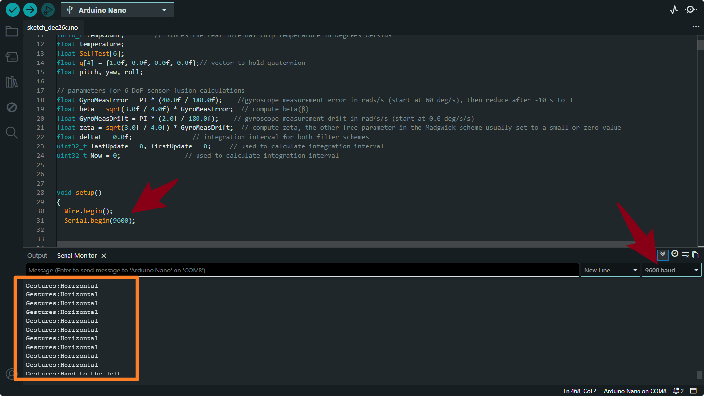
Gestures:Horizontal
Meaning: The sensor is lying flat (level with the ground).
Trigger: Both Pitch and Roll are small (between -40° and 40°).
Gestures:Hand to the left
Meaning: You have tilted the sensor to the Left.
Trigger: Pitch is between -40° and -90°.
Gestures:Hand to the right
Meaning: You have tilted the sensor to the Right.
Trigger: Pitch is between 40° and 90°.
Gestures:Hand down
Meaning: You have tilted the sensor Downwards (pointing down).
Trigger: Roll is between -40° and -90°.
Gestures:Hand up
Meaning: You have tilted the sensor Upwards (pointing up).
Trigger: Roll is between 20° and 90°.
Project 5 Gesture-Controlled Mecanum-Wheel Car
1.Project Overview
The glove reads Pitch/Roll attitude angles via the MPU-6050 and wirelessly sends gesture characters from the BT24 (master) to the car-side BT24 (slave).
The car-side Arduino receives a character and drives the four mecanum-wheel motors to achieve omni-directional motion.
A mecanum car supports combinations such as forward, backward, turn left/right, side-move, diagonal-move, and in-place rotation.

Mecanum-car product link: keyestudio mecanum robot
2.System Components
Module |
Key Parts |
Function |
|---|---|---|
Glove Side |
Nano MPU-6050 BT24 Bluetooth (master) |
Read attitude → send command |
Car Side |
UNO TB6612 motor driver 4 × geared DC motor + mecanum wheel BT24 Bluetooth (slave) |
Parse command → drive motors |
Default serial baud-rate : 9600 bps.
3.Main Control-System Flowchart

4.Example Code
Upload the glove code and the car code separately. Then we can control the car’s forward, backward, left, and right movements using the glove’s posture.
Glove Code
#include "Wire.h"
#include "MPU6050.h"

MPU6050lib mpu;
float aRes, gRes;        // scale resolutions per LSB for the sensors.

int16_t accelCount[3];      // Stores the 16-bit signed accelerometer sensor output.
int16_t gyroCount[3];      // Stores the 16-bit signed gyro sensor output.

float SelfTest[6];
float gyroBias[3] = {0, 0, 0};
float accelBias[3] = {0, 0, 0}; // Bias corrections for gyro and accelerometer.
float q[4] = {1.0f, 0.0f, 0.0f, 0.0f};// vector to hold quaternion.
float pitch, yaw, roll;

// parameters for 6 DoF sensor fusion calculations.
float GyroMeasError = PI * (40.0f / 180.0f);    // gyroscope measurement error in rads/s (start at 60 deg/s), then reduce after ~10 s to 3.
float beta = sqrt(3.0f / 4.0f) * GyroMeasError;  // compute beta(β).
float GyroMeasDrift = PI * (2.0f / 180.0f);    // gyroscope measurement drift in rad/s/s (start at 0.0 deg/s/s).
float zeta = sqrt(3.0f / 4.0f) * GyroMeasDrift;  // compute zeta, the other free parameter in the Madgwick scheme usually set to a small or zero value.
float deltat = 0.0f;                // integration interval for both filter schemes.

uint32_t lastUpdate = 0, firstUpdate = 0;     // used to calculate integration interval.
uint32_t Now = 0;                 // used to calculate integration interval.
double ax,ay,az; // Output of the filter.
double gyrox,gyroy,gyroz; // Output of the filter.

int btnA = 7; // Define two buttons.
int btnB = 8;
int btnAv = 0;  // Acquire the two button values.
int btnBv = 0;

void setup()
{
  Wire.begin();
  Serial.begin(115200);
  uint8_t c = mpu.readByte(MPU6050_ADDRESS, WHO_AM_I_MPU6050);  // Read WHO_AM_I register for MPU-6050.

  Serial.print("I AM ");
  Serial.println(c, HEX);
  mpu.settings(AFS_8G, GFS_250DPS);

 	if (c == 0x68) // WHO_AM_I should always be 0x68
  {
		Serial.println("MPU6050 is online...");// Start by performing self test and reporting values
    mpu.MPU6050SelfTest(SelfTest);
    Serial.print("x-axis self test: acceleration trim within : ");
    Serial.print(SelfTest[0],1);
    Serial.println("% of factory value");

  	Serial.print("y-axis self test: acceleration trim within : ");
  	Serial.print(SelfTest[1],1);
  	Serial.println("% of factory value");

  	Serial.print("z-axis self test: acceleration trim within : ");
  	Serial.print(SelfTest[2],1);
  	Serial.println("% of factory value");

  	Serial.print("x-axis self test: gyration trim within : ");
  	Serial.print(SelfTest[3],1);
  	Serial.println("% of factory value");

  	Serial.print("y-axis self test: gyration trim within : ");
  	Serial.print(SelfTest[4],1);
  	Serial.println("% of factory value");

  	Serial.print("z-axis self test: gyration trim within : ");
  	Serial.print(SelfTest[5],1);
  	Serial.println("% of factory value");

  	if (SelfTest[0] < 1.0f && SelfTest[1] < 1.0f && SelfTest[2] < 1.0f && SelfTest[3] < 1.0f && SelfTest[4] < 1.0f && SelfTest[5] < 1.0f)
  	{
  	  Serial.println("Pass Selftest!");// Calibrate gyro and accelerometers, load biases in bias registers.
	  mpu.calibrateMPU6050(gyroBias, accelBias);
	  Serial.println("MPU6050 bias");
   	  Serial.println(" x\t  y\t  z  ");
      Serial.print((int)(1000 * accelBias[0])); Serial.print('\t');
      Serial.print((int)(1000 * accelBias[1])); Serial.print('\t');
      Serial.print((int)(1000 * accelBias[2]));
      Serial.println(" mg");

      Serial.print(gyroBias[0], 1); Serial.print('\t');
      Serial.print(gyroBias[1], 1); Serial.print('\t');
      Serial.print(gyroBias[2], 1);
      Serial.println(" o/s");

      mpu.settings(AFS_8G, GFS_2000DPS);
      mpu.initMPU6050();

   		// Initialize device for active mode read of accelerometer , gyroscope, and temperature.
		  Serial.println("MPU6050 initialized for active data mode....");
    }
  }
  else
  {
    Serial.print("Could not connect to MPU6050: 0x");
    Serial.println(c, HEX);
    while(1); // Loop forever if communication doesn't happen.
  }

  for(int i = 0; i < 300;i++)
  {
	  if (mpu.readByte(MPU6050_ADDRESS, INT_STATUS) & 0x01)  // check if data ready interrupt.
	  {
      mpu.readAccelData(accelCount);   // Read the x/y/z adc values
      mpu.readGyroData(gyroCount);    // Read the x/y/z adc values
    }
  }
}

void loop()
{
   // If data ready bit set, all data registers have new data.
  if (mpu.readByte(MPU6050_ADDRESS, INT_STATUS) & 0x01)  // check if data ready interrupt.
  {
  	mpu.readAccelData(accelCount);   // Read the x/y/z adc values.
    // Kalman_Filter(accelCount[0],accelCount[1],accelCount[2]);
    // Now we'll calculate the accleration value into actual g's.

    aRes = mpu.getAres();// Acquire the converted value.
    ax = (float)accelCount[0] * aRes; // get actual g value, this depends on scale being set.
    ay = (float)accelCount[1] * aRes;
    az = (float)accelCount[2] * aRes;

    mpu.readGyroData(gyroCount);    // Read the x/y/z adc values
    // Kalman_Filter(gyroCount[0],gyroCount[1],gyroCount[2]);
    gRes = mpu.getGres();       //Acquire the converted value
   // Calculate the gyro value into actual degrees per second
    gyrox = (float)gyroCount[0] * gRes;// get actual gyro value, this depends on scale being set.
    gyroy = (float)gyroCount[1] * gRes;
    gyroz = (float)gyroCount[2] * gRes;
  }

  // Acquire the current time of the system in ms.
  Now = micros();
  // set integration time by time elapsed since last filter update
  deltat = ((Now - lastUpdate) / 1000000.0f);
  lastUpdate = Now;

  if(lastUpdate - firstUpdate > 10000000uL)
  {
    beta = 0.041; // decrease filter gain after stabilized.
    zeta = 0.015; // increase gyro bias drift gain after stabilized.
  }

  // Convert the gyro data to radians
  gyrox = gyrox  * PI / 180.0f;
  gyroy = gyroy * PI / 180.0f;
  gyroz = gyroz * PI / 180.0f;
  // Quaternion conversion function
  MadgwickQuaternionUpdate(ax, ay, az, gyrox, gyroy, gyroz);
  // yaw  = atan2(2.0f * (q[1] * q[2] + q[0] * q[3]), q[0] * q[0] + q[1] * q[1] - q[2] * q[2] - q[3] * q[3]);

  pitch = -asin(2.0f * (q[1] * q[3] - q[0] * q[2]));
  roll  = atan2(2.0f * (q[0] * q[1] + q[2] * q[3]), q[0] * q[0] - q[1] * q[1] - q[2] * q[2] + q[3] * q[3]);

  pitch *= 180.0f / PI;
  yaw  *= 180.0f / PI;
  roll  *= 180.0f / PI;

  //Button A
  if(!digitalRead(btnA))
  {
    delay(100);
    if(!digitalRead(btnA))
    {
      btnAv = ~btnAv;
    }
  }

  //Button B
  if(!digitalRead(btnB))
  {
    delay(100);
    if(!digitalRead(btnB))
    {
      btnBv = ~btnBv;
    }
  }

  // Serial.print("roll:");Serial.println(roll);
  // Serial.print("pitch:");Serial.println(pitch);

  if(btnAv == -1) Serial.println("t");//light up the colorful LED开七彩灯
  else Serial.print("u");//turn on the colorful LED

  if(btnBv == -1) Serial.println("m");// toggle the color of 2812
  else Serial.print("o");//turn off the 2812

  if(40 >= pitch && pitch >= -40 && 40 >= roll && roll >= -40)
  {
    Serial.print("s");//stop
  }
  else if (-40 >= pitch && pitch >= -60&& 40 >= roll && roll >= -40)
  {
    Serial.print("b");//turn left
  }
  else if(-60 >= pitch && pitch >= -120&& 40 >= roll && roll >= -40)
  {
      Serial.print("k");//move left
  }
  else if (60>= pitch && pitch >= 40&& 40 >= roll && roll >= -40)
  {
    Serial.print("d");//turn right
  }
  else if(120 >= pitch && pitch >= 60&& 40 >= roll && roll >= -40)
  {
    Serial.print("h");//move right
  }
  else if (-40 >= roll && roll >= -60&& 40 >= pitch && pitch >= -40)
  {
    Serial.print("c");// go backwards
  }
  else if(-60 >= roll && roll >= -120&& 40 >= pitch && pitch >= -40)
  {
    Serial.print("f");//drift
  }
  else if (60 >= roll && roll >= 40&& 40 >= pitch && pitch >= -40)
  {
      Serial.print("a");//go forwards
  }
  else if(120 >= roll && roll >= 60&& 40 >= pitch && pitch >= -40)
  {
      Serial.print("e");//drift
  }
  delay(50);
}

// Implementation of Sebastian Madgwick's "...efficient orientation filter for... inertial/magnetic sensor arrays".
// which fuses acceleration and rotation rate to produce a quaternion-based estimate of relative.
// device orientation -- which can be converted to yaw, pitch, and roll. Useful for stabilizing quadcopters, etc.
// The performance of the orientation filter is at least as good as conventional Kalman-based filtering algorithms.
// but is much less computationally intensive---it can be performed on a 3.3 V Pro Mini operating at 8 MHz!

void MadgwickQuaternionUpdate(float ax, float ay, float az, float gyrox, float gyroy, float gyroz)
{
 	float q1 = q[0], q2 = q[1], q3 = q[2], q4 = q[3];     // short name local variable for readability.
  float norm;                        // vector norm
  float f1, f2, f3;                     // objective function elements
  float J_11or24, J_12or23, J_13or22, J_14or21, J_32, J_33; // objective function Jacobian elements
  float qDot1, qDot2, qDot3, qDot4;
  float hatDot1, hatDot2, hatDot3, hatDot4;
  float gerrx, gerry, gerrz, gbiasx, gbiasy, gbiasz;     // gyro bias error

  // Auxiliary variables to avoid repeated arithmetic
  float _halfq1 = 0.5f * q1;
  float _halfq2 = 0.5f * q2;
  float _halfq3 = 0.5f * q3;
  float _halfq4 = 0.5f * q4;
  float _2q1 = 2.0f * q1;
  float _2q2 = 2.0f * q2;
  float _2q3 = 2.0f * q3;
  float _2q4 = 2.0f * q4;
  float _2q1q3 = 2.0f * q1 * q3;
  float _2q3q4 = 2.0f * q3 * q4;

  // Normalise accelerometer measurement.
  norm = sqrt(ax * ax + ay * ay + az * az);
  if (norm == 0.0f) return; // handle NaN
  norm = 1.0f/norm;
  ax *= norm;
  ay *= norm;
  az *= norm;

  // Compute the objective function and Jacobian
  f1 = _2q2 * q4 - _2q1 * q3 - ax;
  f2 = _2q1 * q2 + _2q3 * q4 - ay;
  f3 = 1.0f - _2q2 * q2 - _2q3 * q3 - az;
  J_11or24 = _2q3;
  J_12or23 = _2q4;
  J_13or22 = _2q1;
  J_14or21 = _2q2;
  J_32 = 2.0f * J_14or21;
  J_33 = 2.0f * J_11or24;

  // Compute the gradient (matrix multiplication)
  hatDot1 = J_14or21 * f2 - J_11or24 * f1;
  hatDot2 = J_12or23 * f1 + J_13or22 * f2 - J_32 * f3;
  hatDot3 = J_12or23 * f2 - J_33 *f3 - J_13or22 * f1;
  hatDot4 = J_14or21 * f1 + J_11or24 * f2;

  // Normalize the gradient
  norm = sqrt(hatDot1 * hatDot1 + hatDot2 * hatDot2 + hatDot3 * hatDot3 + hatDot4 * hatDot4);
  hatDot1 /= norm;
  hatDot2 /= norm;
  hatDot3 /= norm;
  hatDot4 /= norm;

  // Compute estimated gyroscope biases
  gerrx = _2q1 * hatDot2 - _2q2 * hatDot1 - _2q3 * hatDot4 + _2q4 * hatDot3;
  gerry = _2q1 * hatDot3 + _2q2 * hatDot4 - _2q3 * hatDot1 - _2q4 * hatDot2;
  gerrz = _2q1 * hatDot4 - _2q2 * hatDot3 + _2q3 * hatDot2 - _2q4 * hatDot1;

  // Compute and remove gyroscope biases
  gbiasx += gerrx * deltat * zeta;
  gbiasy += gerry * deltat * zeta;
  gbiasz += gerrz * deltat * zeta;
  gyrox -= gbiasx;
  gyroy -= gbiasy;
  gyroz -= gbiasz;

  // Compute the quaternion derivative
  qDot1 = -_halfq2 * gyrox - _halfq3 * gyroy - _halfq4 * gyroz;
  qDot2 =  _halfq1 * gyrox + _halfq3 * gyroz - _halfq4 * gyroy;
  qDot3 =  _halfq1 * gyroy - _halfq2 * gyroz + _halfq4 * gyrox;
  qDot4 =  _halfq1 * gyroz + _halfq2 * gyroy - _halfq3 * gyrox;

  // Compute then integrate estimated quaternion derivative
  q1 += (qDot1 -(beta * hatDot1)) * deltat;
  q2 += (qDot2 -(beta * hatDot2)) * deltat;
  q3 += (qDot3 -(beta * hatDot3)) * deltat;
  q4 += (qDot4 -(beta * hatDot4)) * deltat;

  // Normalize the quaternion
  norm = sqrt(q1 * q1 + q2 * q2 + q3 * q3 + q4 * q4);   // normalise quaternion
  norm = 1.0f/norm;
  q[0] = q1 * norm;
  q[1] = q2 * norm;
  q[2] = q3 * norm;
  q[3] = q4 * norm;
}
Car Code
Here we need to import the library file MecanumCar_v2.Click to download
/*
  Keyestudio 4WD Mecanum Robot
*/

#include "MecanumCar_v2.h"

// 1. Variable Definitions
mecanumCar mecanumCar(3, 2);   // SDA=D3, SCL=D2
char cmd;
String valStr;

// 2. External Speed Variable Declarations
extern uint8_t speed_Upper_R;
extern uint8_t speed_Lower_R;
extern uint8_t speed_Upper_L;
extern uint8_t speed_Lower_L;

void setup()
{
  // Important: The baud rate must match the sender!
  Serial.begin(9600);
  mecanumCar.Init();
  mecanumCar.Stop();
  Serial.println(F("Robot Ready..."));
}

void loop()
{
  if (Serial.available() > 0)
  {
    cmd = Serial.read();

    // Filter out invisible interference characters
    if (cmd == '\n' || cmd == '\r' || (byte)cmd == 0xFF) return;

    // Print the received command
    Serial.print("Recv: ");
    Serial.println(cmd);

    switch (cmd)
    {
      /* ---- Motion Control ---- */
      case 's': mecanumCar.Stop();        break;
      case 'a': mecanumCar.Advance();     break;
      case 'c': mecanumCar.Back();        break;
      case 'b': mecanumCar.Turn_Left();   break;
      case 'd': mecanumCar.Turn_Right();  break;
      case 'k': mecanumCar.L_Move();      break;
      case 'h': mecanumCar.R_Move();      break;
      case 'e': mecanumCar.drift_left();  break;
      case 'f': mecanumCar.drift_right(); break;

      /* ---- Speed Adjustment Commands (e.g., send v80#) ---- */
      case 'v': case 'w': case 'x': case 'y':
        delay(10); // Wait for data in the buffer
        valStr = Serial.readStringUntil('#');
        if (valStr.length() > 0) {
          int mappedSpeed = map(valStr.toInt(), 0, 100, 0, 255);
          if (cmd == 'v') speed_Upper_L = mappedSpeed;
          if (cmd == 'w') speed_Lower_L = mappedSpeed;
          if (cmd == 'x') speed_Upper_R = mappedSpeed;
          if (cmd == 'y') speed_Lower_R = mappedSpeed;
        }
        break;
    }
  }
}
6.Gesture Recognition & Command Mapping
After uploading the code, we can control the movement of the small car. Refer to the table below to understand the characters sent by the glove offset and their corresponding car postures.
Gesture Set 1 (±40° – 60°, fine control)
Gesture |
Euler Angle |
Sent Char |
Car Action |
|---|---|---|---|
Hand up (40°-60°) |
−40° ≥ pitch ≥ −60° |
|
Forward |
Hand down (40°-60°) |
40° ≤ pitch ≤ 60° |
|
Backward |
Tilt left (40°-60°) |
−40° ≥ roll ≥ −60° |
|
Turn left |
Tilt right (40°-60°) |
40° ≤ roll ≤ 60° |
|
Turn right |
Level |
— |
|
Brake / Stop |
Gesture Set 2 (±60° – 120°, wide motion)
Gesture |
Euler Angle |
Sent Char |
Car Action |
|---|---|---|---|
Hand up (60°-120°) |
−60° ≥ pitch ≥ −120° |
|
Drift left |
Hand down (60°-120°) |
60° ≤ pitch ≤ 120° |
|
Drift right |
Tilt left (60°-120°) |
−60° ≥ roll ≥ −120° |
|
Strafe left |
Tilt right (60°-120°) |
60° ≤ roll ≤ 120° |
|
Strafe right |
Car-Side Command Table
Received Char |
Function |
Received Char |
Function |
|---|---|---|---|
|
Stop |
|
Strafe right |
|
Forward |
|
Strafe left |
|
Backward |
|
Drift left |
|
Turn left |
|
Drift right |
|
Turn right |
|
Diagonal moves |
|
Independent wheel speed |
|
Other extended functions |