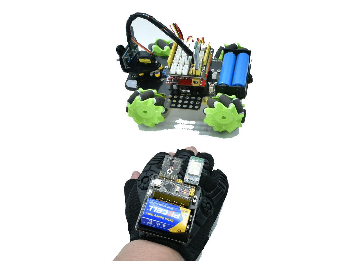
Project 5 Gesture-Controlled Mecanum-Wheel Car
1.Project Overview
The glove reads Pitch/Roll attitude angles via the MPU-6050 and wirelessly sends gesture characters from the BT24 (master) to the car-side BT24 (slave).
The car-side Arduino receives a character and drives the four mecanum-wheel motors to achieve omni-directional motion.
A mecanum car supports combinations such as forward, backward, turn left/right, side-move, diagonal-move, and in-place rotation.
Mecanum-car product link: keyestudio mecanum robot
2.System Components
Module |
Key Parts |
Function |
|---|---|---|
Glove Side |
Nano MPU-6050 BT24 Bluetooth (master) |
Read attitude → send command |
Car Side |
UNO TB6612 motor driver 4 × geared DC motor + mecanum wheel BT24 Bluetooth (slave) |
Parse command → drive motors |
Default serial baud-rate : 9600 bps.
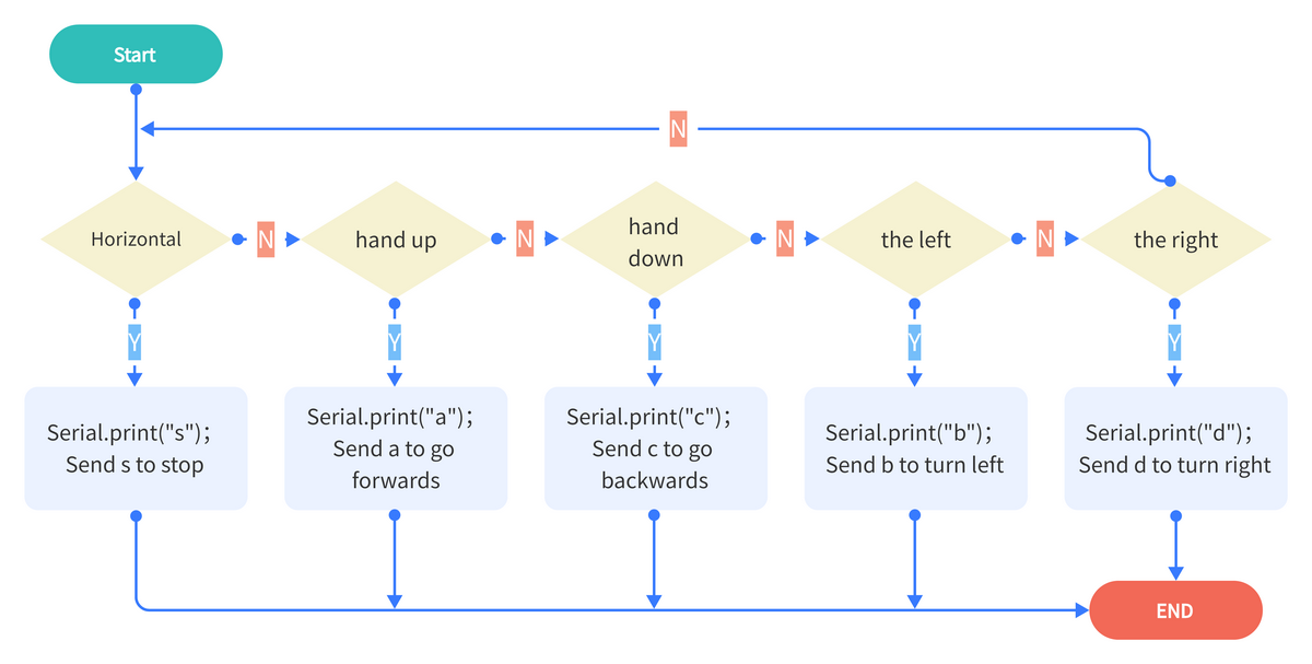
3.Main Control-System Flowchart
4.Example Code
Upload the glove code and the car code separately. Then we can control the car’s forward, backward, left, and right movements using the glove’s posture.
Glove Code
#include "Wire.h"
#include "MPU6050.h"

MPU6050lib mpu;
float aRes, gRes;        // scale resolutions per LSB for the sensors.

int16_t accelCount[3];      // Stores the 16-bit signed accelerometer sensor output.
int16_t gyroCount[3];      // Stores the 16-bit signed gyro sensor output.

float SelfTest[6];
float gyroBias[3] = {0, 0, 0};
float accelBias[3] = {0, 0, 0}; // Bias corrections for gyro and accelerometer.
float q[4] = {1.0f, 0.0f, 0.0f, 0.0f};// vector to hold quaternion.
float pitch, yaw, roll;

// parameters for 6 DoF sensor fusion calculations.
float GyroMeasError = PI * (40.0f / 180.0f);    // gyroscope measurement error in rads/s (start at 60 deg/s), then reduce after ~10 s to 3.
float beta = sqrt(3.0f / 4.0f) * GyroMeasError;  // compute beta(β).
float GyroMeasDrift = PI * (2.0f / 180.0f);    // gyroscope measurement drift in rad/s/s (start at 0.0 deg/s/s).
float zeta = sqrt(3.0f / 4.0f) * GyroMeasDrift;  // compute zeta, the other free parameter in the Madgwick scheme usually set to a small or zero value.
float deltat = 0.0f;                // integration interval for both filter schemes.

uint32_t lastUpdate = 0, firstUpdate = 0;     // used to calculate integration interval.
uint32_t Now = 0;                 // used to calculate integration interval.
double ax,ay,az; // Output of the filter.
double gyrox,gyroy,gyroz; // Output of the filter.

int btnA = 7; // Define two buttons.
int btnB = 8;
int btnAv = 0;  // Acquire the two button values.
int btnBv = 0;

void setup()
{
  Wire.begin();
  Serial.begin(115200);
  uint8_t c = mpu.readByte(MPU6050_ADDRESS, WHO_AM_I_MPU6050);  // Read WHO_AM_I register for MPU-6050.

  Serial.print("I AM ");
  Serial.println(c, HEX);
  mpu.settings(AFS_8G, GFS_250DPS);

 	if (c == 0x68) // WHO_AM_I should always be 0x68
  {
		Serial.println("MPU6050 is online...");// Start by performing self test and reporting values
    mpu.MPU6050SelfTest(SelfTest);
    Serial.print("x-axis self test: acceleration trim within : ");
    Serial.print(SelfTest[0],1);
    Serial.println("% of factory value");

  	Serial.print("y-axis self test: acceleration trim within : ");
  	Serial.print(SelfTest[1],1);
  	Serial.println("% of factory value");

  	Serial.print("z-axis self test: acceleration trim within : ");
  	Serial.print(SelfTest[2],1);
  	Serial.println("% of factory value");

  	Serial.print("x-axis self test: gyration trim within : ");
  	Serial.print(SelfTest[3],1);
  	Serial.println("% of factory value");

  	Serial.print("y-axis self test: gyration trim within : ");
  	Serial.print(SelfTest[4],1);
  	Serial.println("% of factory value");

  	Serial.print("z-axis self test: gyration trim within : ");
  	Serial.print(SelfTest[5],1);
  	Serial.println("% of factory value");

  	if (SelfTest[0] < 1.0f && SelfTest[1] < 1.0f && SelfTest[2] < 1.0f && SelfTest[3] < 1.0f && SelfTest[4] < 1.0f && SelfTest[5] < 1.0f)
  	{
  	  Serial.println("Pass Selftest!");// Calibrate gyro and accelerometers, load biases in bias registers.
	  mpu.calibrateMPU6050(gyroBias, accelBias);
	  Serial.println("MPU6050 bias");
   	  Serial.println(" x\t  y\t  z  ");
      Serial.print((int)(1000 * accelBias[0])); Serial.print('\t');
      Serial.print((int)(1000 * accelBias[1])); Serial.print('\t');
      Serial.print((int)(1000 * accelBias[2]));
      Serial.println(" mg");

      Serial.print(gyroBias[0], 1); Serial.print('\t');
      Serial.print(gyroBias[1], 1); Serial.print('\t');
      Serial.print(gyroBias[2], 1);
      Serial.println(" o/s");

      mpu.settings(AFS_8G, GFS_2000DPS);
      mpu.initMPU6050();

   		// Initialize device for active mode read of accelerometer , gyroscope, and temperature.
		  Serial.println("MPU6050 initialized for active data mode....");
    }
  }
  else
  {
    Serial.print("Could not connect to MPU6050: 0x");
    Serial.println(c, HEX);
    while(1); // Loop forever if communication doesn't happen.
  }

  for(int i = 0; i < 300;i++)
  {
	  if (mpu.readByte(MPU6050_ADDRESS, INT_STATUS) & 0x01)  // check if data ready interrupt.
	  {
      mpu.readAccelData(accelCount);   // Read the x/y/z adc values
      mpu.readGyroData(gyroCount);    // Read the x/y/z adc values
    }
  }
}

void loop()
{
   // If data ready bit set, all data registers have new data.
  if (mpu.readByte(MPU6050_ADDRESS, INT_STATUS) & 0x01)  // check if data ready interrupt.
  {
  	mpu.readAccelData(accelCount);   // Read the x/y/z adc values.
    // Kalman_Filter(accelCount[0],accelCount[1],accelCount[2]);
    // Now we'll calculate the accleration value into actual g's.

    aRes = mpu.getAres();// Acquire the converted value.
    ax = (float)accelCount[0] * aRes; // get actual g value, this depends on scale being set.
    ay = (float)accelCount[1] * aRes;
    az = (float)accelCount[2] * aRes;

    mpu.readGyroData(gyroCount);    // Read the x/y/z adc values
    // Kalman_Filter(gyroCount[0],gyroCount[1],gyroCount[2]);
    gRes = mpu.getGres();       //Acquire the converted value
   // Calculate the gyro value into actual degrees per second
    gyrox = (float)gyroCount[0] * gRes;// get actual gyro value, this depends on scale being set.
    gyroy = (float)gyroCount[1] * gRes;
    gyroz = (float)gyroCount[2] * gRes;
  }

  // Acquire the current time of the system in ms.
  Now = micros();
  // set integration time by time elapsed since last filter update
  deltat = ((Now - lastUpdate) / 1000000.0f);
  lastUpdate = Now;

  if(lastUpdate - firstUpdate > 10000000uL)
  {
    beta = 0.041; // decrease filter gain after stabilized.
    zeta = 0.015; // increase gyro bias drift gain after stabilized.
  }

  // Convert the gyro data to radians
  gyrox = gyrox  * PI / 180.0f;
  gyroy = gyroy * PI / 180.0f;
  gyroz = gyroz * PI / 180.0f;
  // Quaternion conversion function
  MadgwickQuaternionUpdate(ax, ay, az, gyrox, gyroy, gyroz);
  // yaw  = atan2(2.0f * (q[1] * q[2] + q[0] * q[3]), q[0] * q[0] + q[1] * q[1] - q[2] * q[2] - q[3] * q[3]);

  pitch = -asin(2.0f * (q[1] * q[3] - q[0] * q[2]));
  roll  = atan2(2.0f * (q[0] * q[1] + q[2] * q[3]), q[0] * q[0] - q[1] * q[1] - q[2] * q[2] + q[3] * q[3]);

  pitch *= 180.0f / PI;
  yaw  *= 180.0f / PI;
  roll  *= 180.0f / PI;

  //Button A
  if(!digitalRead(btnA))
  {
    delay(100);
    if(!digitalRead(btnA))
    {
      btnAv = ~btnAv;
    }
  }

  //Button B
  if(!digitalRead(btnB))
  {
    delay(100);
    if(!digitalRead(btnB))
    {
      btnBv = ~btnBv;
    }
  }

  // Serial.print("roll:");Serial.println(roll);
  // Serial.print("pitch:");Serial.println(pitch);

  if(btnAv == -1) Serial.println("t");//light up the colorful LED开七彩灯
  else Serial.print("u");//turn on the colorful LED

  if(btnBv == -1) Serial.println("m");// toggle the color of 2812
  else Serial.print("o");//turn off the 2812

  if(40 >= pitch && pitch >= -40 && 40 >= roll && roll >= -40)
  {
    Serial.print("s");//stop
  }
  else if (-40 >= pitch && pitch >= -60&& 40 >= roll && roll >= -40)
  {
    Serial.print("b");//turn left
  }
  else if(-60 >= pitch && pitch >= -120&& 40 >= roll && roll >= -40)
  {
      Serial.print("k");//move left
  }
  else if (60>= pitch && pitch >= 40&& 40 >= roll && roll >= -40)
  {
    Serial.print("d");//turn right
  }
  else if(120 >= pitch && pitch >= 60&& 40 >= roll && roll >= -40)
  {
    Serial.print("h");//move right
  }
  else if (-40 >= roll && roll >= -60&& 40 >= pitch && pitch >= -40)
  {
    Serial.print("c");// go backwards
  }
  else if(-60 >= roll && roll >= -120&& 40 >= pitch && pitch >= -40)
  {
    Serial.print("f");//drift
  }
  else if (60 >= roll && roll >= 40&& 40 >= pitch && pitch >= -40)
  {
      Serial.print("a");//go forwards
  }
  else if(120 >= roll && roll >= 60&& 40 >= pitch && pitch >= -40)
  {
      Serial.print("e");//drift
  }
  delay(50);
}

// Implementation of Sebastian Madgwick's "...efficient orientation filter for... inertial/magnetic sensor arrays".
// which fuses acceleration and rotation rate to produce a quaternion-based estimate of relative.
// device orientation -- which can be converted to yaw, pitch, and roll. Useful for stabilizing quadcopters, etc.
// The performance of the orientation filter is at least as good as conventional Kalman-based filtering algorithms.
// but is much less computationally intensive---it can be performed on a 3.3 V Pro Mini operating at 8 MHz!

void MadgwickQuaternionUpdate(float ax, float ay, float az, float gyrox, float gyroy, float gyroz)
{
 	float q1 = q[0], q2 = q[1], q3 = q[2], q4 = q[3];     // short name local variable for readability.
  float norm;                        // vector norm
  float f1, f2, f3;                     // objective function elements
  float J_11or24, J_12or23, J_13or22, J_14or21, J_32, J_33; // objective function Jacobian elements
  float qDot1, qDot2, qDot3, qDot4;
  float hatDot1, hatDot2, hatDot3, hatDot4;
  float gerrx, gerry, gerrz, gbiasx, gbiasy, gbiasz;     // gyro bias error

  // Auxiliary variables to avoid repeated arithmetic
  float _halfq1 = 0.5f * q1;
  float _halfq2 = 0.5f * q2;
  float _halfq3 = 0.5f * q3;
  float _halfq4 = 0.5f * q4;
  float _2q1 = 2.0f * q1;
  float _2q2 = 2.0f * q2;
  float _2q3 = 2.0f * q3;
  float _2q4 = 2.0f * q4;
  float _2q1q3 = 2.0f * q1 * q3;
  float _2q3q4 = 2.0f * q3 * q4;

  // Normalise accelerometer measurement.
  norm = sqrt(ax * ax + ay * ay + az * az);
  if (norm == 0.0f) return; // handle NaN
  norm = 1.0f/norm;
  ax *= norm;
  ay *= norm;
  az *= norm;

  // Compute the objective function and Jacobian
  f1 = _2q2 * q4 - _2q1 * q3 - ax;
  f2 = _2q1 * q2 + _2q3 * q4 - ay;
  f3 = 1.0f - _2q2 * q2 - _2q3 * q3 - az;
  J_11or24 = _2q3;
  J_12or23 = _2q4;
  J_13or22 = _2q1;
  J_14or21 = _2q2;
  J_32 = 2.0f * J_14or21;
  J_33 = 2.0f * J_11or24;

  // Compute the gradient (matrix multiplication)
  hatDot1 = J_14or21 * f2 - J_11or24 * f1;
  hatDot2 = J_12or23 * f1 + J_13or22 * f2 - J_32 * f3;
  hatDot3 = J_12or23 * f2 - J_33 *f3 - J_13or22 * f1;
  hatDot4 = J_14or21 * f1 + J_11or24 * f2;

  // Normalize the gradient
  norm = sqrt(hatDot1 * hatDot1 + hatDot2 * hatDot2 + hatDot3 * hatDot3 + hatDot4 * hatDot4);
  hatDot1 /= norm;
  hatDot2 /= norm;
  hatDot3 /= norm;
  hatDot4 /= norm;

  // Compute estimated gyroscope biases
  gerrx = _2q1 * hatDot2 - _2q2 * hatDot1 - _2q3 * hatDot4 + _2q4 * hatDot3;
  gerry = _2q1 * hatDot3 + _2q2 * hatDot4 - _2q3 * hatDot1 - _2q4 * hatDot2;
  gerrz = _2q1 * hatDot4 - _2q2 * hatDot3 + _2q3 * hatDot2 - _2q4 * hatDot1;

  // Compute and remove gyroscope biases
  gbiasx += gerrx * deltat * zeta;
  gbiasy += gerry * deltat * zeta;
  gbiasz += gerrz * deltat * zeta;
  gyrox -= gbiasx;
  gyroy -= gbiasy;
  gyroz -= gbiasz;

  // Compute the quaternion derivative
  qDot1 = -_halfq2 * gyrox - _halfq3 * gyroy - _halfq4 * gyroz;
  qDot2 =  _halfq1 * gyrox + _halfq3 * gyroz - _halfq4 * gyroy;
  qDot3 =  _halfq1 * gyroy - _halfq2 * gyroz + _halfq4 * gyrox;
  qDot4 =  _halfq1 * gyroz + _halfq2 * gyroy - _halfq3 * gyrox;

  // Compute then integrate estimated quaternion derivative
  q1 += (qDot1 -(beta * hatDot1)) * deltat;
  q2 += (qDot2 -(beta * hatDot2)) * deltat;
  q3 += (qDot3 -(beta * hatDot3)) * deltat;
  q4 += (qDot4 -(beta * hatDot4)) * deltat;

  // Normalize the quaternion
  norm = sqrt(q1 * q1 + q2 * q2 + q3 * q3 + q4 * q4);   // normalise quaternion
  norm = 1.0f/norm;
  q[0] = q1 * norm;
  q[1] = q2 * norm;
  q[2] = q3 * norm;
  q[3] = q4 * norm;
}
Car Code
Here we need to import the library file MecanumCar_v2.Click to download
/*
  Keyestudio 4WD Mecanum Robot
*/

#include "MecanumCar_v2.h"

// 1. Variable Definitions
mecanumCar mecanumCar(3, 2);   // SDA=D3, SCL=D2
char cmd;
String valStr;

// 2. External Speed Variable Declarations
extern uint8_t speed_Upper_R;
extern uint8_t speed_Lower_R;
extern uint8_t speed_Upper_L;
extern uint8_t speed_Lower_L;

void setup()
{
  // Important: The baud rate must match the sender!
  Serial.begin(9600);
  mecanumCar.Init();
  mecanumCar.Stop();
  Serial.println(F("Robot Ready..."));
}

void loop()
{
  if (Serial.available() > 0)
  {
    cmd = Serial.read();

    // Filter out invisible interference characters
    if (cmd == '\n' || cmd == '\r' || (byte)cmd == 0xFF) return;

    // Print the received command
    Serial.print("Recv: ");
    Serial.println(cmd);

    switch (cmd)
    {
      /* ---- Motion Control ---- */
      case 's': mecanumCar.Stop();        break;
      case 'a': mecanumCar.Advance();     break;
      case 'c': mecanumCar.Back();        break;
      case 'b': mecanumCar.Turn_Left();   break;
      case 'd': mecanumCar.Turn_Right();  break;
      case 'k': mecanumCar.L_Move();      break;
      case 'h': mecanumCar.R_Move();      break;
      case 'e': mecanumCar.drift_left();  break;
      case 'f': mecanumCar.drift_right(); break;

      /* ---- Speed Adjustment Commands (e.g., send v80#) ---- */
      case 'v': case 'w': case 'x': case 'y':
        delay(10); // Wait for data in the buffer
        valStr = Serial.readStringUntil('#');
        if (valStr.length() > 0) {
          int mappedSpeed = map(valStr.toInt(), 0, 100, 0, 255);
          if (cmd == 'v') speed_Upper_L = mappedSpeed;
          if (cmd == 'w') speed_Lower_L = mappedSpeed;
          if (cmd == 'x') speed_Upper_R = mappedSpeed;
          if (cmd == 'y') speed_Lower_R = mappedSpeed;
        }
        break;
    }
  }
}
6.Gesture Recognition & Command Mapping
After uploading the code, we can control the movement of the small car. Refer to the table below to understand the characters sent by the glove offset and their corresponding car postures.
Gesture Set 1 (±40° – 60°, fine control)
Gesture |
Euler Angle |
Sent Char |
Car Action |
|---|---|---|---|
Hand up (40°-60°) |
−40° ≥ pitch ≥ −60° |
|
Forward |
Hand down (40°-60°) |
40° ≤ pitch ≤ 60° |
|
Backward |
Tilt left (40°-60°) |
−40° ≥ roll ≥ −60° |
|
Turn left |
Tilt right (40°-60°) |
40° ≤ roll ≤ 60° |
|
Turn right |
Level |
— |
|
Brake / Stop |
Gesture Set 2 (±60° – 120°, wide motion)
Gesture |
Euler Angle |
Sent Char |
Car Action |
|---|---|---|---|
Hand up (60°-120°) |
−60° ≥ pitch ≥ −120° |
|
Drift left |
Hand down (60°-120°) |
60° ≤ pitch ≤ 120° |
|
Drift right |
Tilt left (60°-120°) |
−60° ≥ roll ≥ −120° |
|
Strafe left |
Tilt right (60°-120°) |
60° ≤ roll ≤ 120° |
|
Strafe right |
Car-Side Command Table
Received Char |
Function |
Received Char |
Function |
|---|---|---|---|
|
Stop |
|
Strafe right |
|
Forward |
|
Strafe left |
|
Backward |
|
Drift left |
|
Turn left |
|
Drift right |
|
Turn right |
|
Diagonal moves |
|
Independent wheel speed |
|
Other extended functions |