Project 30: Joystick Motion Control
Description
This project demonstrates how to use an Arduino to read the analog signals from a dual-axis joystick module and manually control the rotation of a stepper motor. By moving the joystick, you can precisely control the stepper motor to rotate forward, reverse, or stop.
This type of control is common in robotic gimbals, manual teaching of robotic arm joints, microscope stage translation, and other automation devices. It serves as an excellent foundational project for understanding “human-machine interaction control.”
Hardware
UNO R3 development board (CH340) × 1
28BYJ-48 Stepper Motor × 1
ULN2003 Stepper Motor Driver Board × 1
Dual-axis Joystick Module × 1
Breadboard × 1
Dupont wires/jumper wires × several
Working Principle
The core of this project is converting the joystick’s output voltage into motion commands for the stepper motor.
Joystick Analog Output: The joystick internally contains two potentiometers (variable resistors). When you push the joystick along the X-axis, the
VRxpin outputs a varying voltage. Arduino reads this voltage through an analog input pin (A0) and converts it into a value between0and1023.Center Position and Thresholds: When the joystick is naturally centered, the reading is approximately
512. In the code, thresholds are set as follows:If the reading is less than 300 (pushed to one side), the stepper motor rotates continuously forward.
If the reading is greater than 800 (pushed to the other side), the stepper motor rotates continuously in reverse.
If the reading is between 300 and 800 (joystick centered/released), the stepper motor stops powering and holds still.
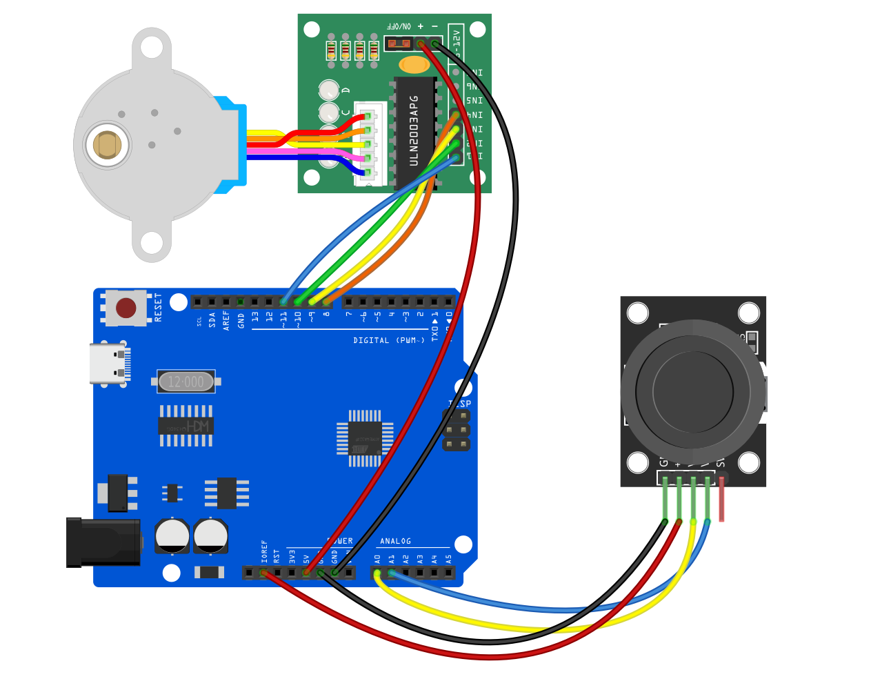
Wiring Diagram
1. Joystick Module
(Note: This project only controls a single-axis stepper motor, so only the X-axis is connected. The Y-axis VRy and button SW pins can be left unconnected.)
VRx (X-axis analog output)➔ Connect to Arduino A0VCC➔ Connect to Arduino 5VGND➔ Connect to Arduino GND
2. Stepper Motor & Driver Board (ULN2003)
Insert the stepper motor’s white connector into the ULN2003 driver board socket.
IN1➔ Connect to Arduino D8IN2➔ Connect to Arduino D10 (Note the sequence: for Arduino’s built-in Stepper library, the order must be 8, 10, 9, 11)IN3➔ Connect to Arduino D9IN4➔ Connect to Arduino D11+ (VCC)➔ Connect to Arduino 5V (or external 5V power supply)- (GND)➔ Connect to Arduino GND
Sample Code
Copy and upload the following code to your Arduino:
/*

Electronics Learning Starter Kit for Arduino

Project 30

Joystick Motion Control

Edit By Keyes

*/

#include <Stepper.h>

// Define the number of steps per revolution for the stepper motor (28BYJ-48 is usually 2048 steps)
const int stepsPerRevolution = 2048;

// Initialize the stepper motor object, note the pin order is 8, 10, 9, 11
Stepper myStepper(stepsPerRevolution, 8, 10, 9, 11);

void setup() {
  // Set the stepper motor speed to 10 RPM (revolutions per minute)
  myStepper.setSpeed(10);

  // Initialize serial communication for monitoring joystick values
  Serial.begin(9600);
}

void loop() {
  // 1. Read the joystick X-axis analog value (range 0 - 1023)
  int xValue = analogRead(A0);

  // Print the current value to the serial monitor for debugging
  Serial.print("Joystick X-axis value: ");
  Serial.println(xValue);

  // 2. Determine joystick direction and control the motor
  if (xValue < 300) {
    // Joystick pushed to one side: step motor forward
    myStepper.step(10);
  }
  else if (xValue > 800) {
    // Joystick pushed to the other side: step motor backward
    myStepper.step(-10);
  }
  else {
    // Joystick in neutral position (300 ~ 800)
    // De-energize all coils to prevent the stepper motor from overheating while idle
    digitalWrite(8, LOW);
    digitalWrite(9, LOW);
    digitalWrite(10, LOW);
    digitalWrite(11, LOW);
  }
}
Code Explanation
Library Inclusion and Initialization: The
#include <Stepper.h>imports the stepper motor control library. The lineStepper myStepper(stepsPerRevolution, 8, 10, 9, 11);defines the control pins. Important: When using this official library with the 28BYJ-48 motor, the middle two pins must be swapped (i.e., 10, 9 instead of 9, 10) to ensure smooth motor rotation.Reading Analog Value:
analogRead(A0)continuously detects the joystick’s tilt, returning a number between 0 and 1023.Motion Response (
step): Each loop iteration moves the motor a small step (10or-10steps). Since the loop runs very fast, holding the joystick in one direction will cause the motor to move continuously and smoothly.Power-Off Protection (
digitalWrite(..., LOW)): Stepper motors tend to lock the shaft when stopped because coils remain energized. To prevent this and reduce heat, when the joystick is centered (released), all four control pins are set to LOW to cut coil current, protecting the motor and driver board from overheating.
Project Result
After uploading the code and powering the circuit:
Neutral State: When the joystick is untouched, it automatically returns to center, and the stepper motor remains still without heating up.
Pushing Left/Down: Moving the joystick to one side (reading < 300) causes the stepper motor to rotate continuously clockwise (or counterclockwise).
Pushing Right/Up: Moving the joystick to the opposite side (reading > 800) immediately reverses the motor’s direction for continuous rotation.
Real-Time Response: When you release the joystick, it springs back to center, and the motor instantly brakes and stops. Opening the serial monitor on your computer allows you to see the joystick’s real-time data changes.