Project 32: Motion-Controlled Servo
Description
In this project, we will combine the MPU6050 6-axis motion sensor with an SG90 Servo motor to create a motion-controlled system. By tilting the MPU6050 module along its X-axis, the Arduino will read the acceleration data, map it to an angle, and command the servo motor to rotate accordingly. This is the basic principle behind gimbal stabilization and motion-controlled robotic arms.
Hardware
UNO R3 development board (ch340) x1
MPU6050 Module x1
SG90 Servo Motor x1
Breadboard x1
Jumper wires
Working Principle
The MPU6050 measures the acceleration of gravity. When the module is perfectly flat, the X and Y axes read 0g, and the Z axis reads 1g. When you tilt the module, the gravity vector is distributed across the axes. By reading the raw acceleration value of the X-axis, we can determine the tilt angle.
The Arduino reads this raw X-axis value (which typically ranges from -17000 to +17000 depending on the tilt) and uses the map() function to convert this range into a degree value between 0 and 180. This degree value is then sent to the Servo motor using the Servo library, causing the motor’s arm to mimic the tilt of the sensor.
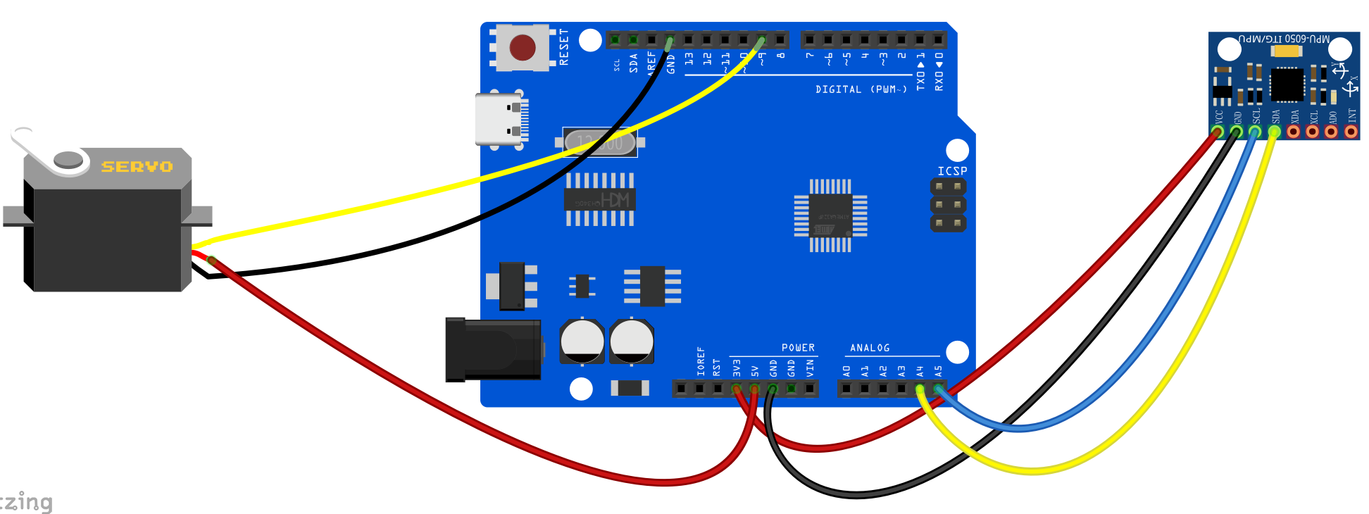
Wiring Diagram
MPU6050:
VCC -> 5V
GND -> GND
SCL -> A5
SDA -> A4
SG90 Servo:
Brown/Black Wire -> GND
Red Wire -> 5V
Orange/Yellow Wire (Signal) -> Digital Pin 9
Sample Code
/*

Electronics Learning Starter Kit for Arduino

Project 32

Motion Controlled Servo

Edit By Keyes

*/

#include <Wire.h>
#include <Servo.h>

const int MPU_addr=0x68;  // I2C address of the MPU-6050
int16_t AcX, AcY, AcZ;

Servo myServo;  // create servo object to control a servo

void setup() {
  Wire.begin();
  Wire.beginTransmission(MPU_addr);
  Wire.write(0x6B);  // PWR_MGMT_1 register
  Wire.write(0);     // set to zero (wakes up the MPU-6050)
  Wire.endTransmission(true);

  myServo.attach(9);  // attaches the servo on pin 9 to the servo object
  Serial.begin(9600);
}

void loop() {
  Wire.beginTransmission(MPU_addr);
  Wire.write(0x3B);  // starting with register 0x3B (ACCEL_XOUT_H)
  Wire.endTransmission(false);
  Wire.requestFrom(MPU_addr, 6, true);  // request a total of 6 registers

  AcX = Wire.read()<<8 | Wire.read();  // 0x3B (ACCEL_XOUT_H) & 0x3C (ACCEL_XOUT_L)
  AcY = Wire.read()<<8 | Wire.read();  // 0x3D (ACCEL_YOUT_H) & 0x3E (ACCEL_YOUT_L)
  AcZ = Wire.read()<<8 | Wire.read();  // 0x3F (ACCEL_ZOUT_H) & 0x40 (ACCEL_ZOUT_L)

  // Map the X-axis acceleration (-17000 to 17000) to Servo angle (0 to 180)
  // Note: You may need to adjust the -17000 and 17000 values based on your specific sensor's calibration
  int servoAngle = map(AcX, -17000, 17000, 0, 180);

  // Constrain the angle to prevent servo damage
  servoAngle = constrain(servoAngle, 0, 180);

  myServo.write(servoAngle);  // tell servo to go to position in variable 'servoAngle'

  Serial.print("AcX: ");
  Serial.print(AcX);
  Serial.print(" => Angle: ");
  Serial.println(servoAngle);

  delay(50);  // small delay for stability
}
Code Explanation
Mapping the Values:
int servoAngle = map(AcX, -17000, 17000, 0, 180);
The map() function takes the raw X-axis acceleration reading (AcX) and scales it from its original range (-17000 to 17000) to the target range for the servo motor (0 to 180 degrees).
Constraining the Angle:
servoAngle = constrain(servoAngle, 0, 180);
The constrain() function ensures that even if the sensor outputs a value slightly outside the expected range, the servoAngle will never drop below 0 or exceed 180. This protects the physical gears inside the servo motor from grinding.
Project Result
After uploading the code, hold the MPU6050 module in your hand. As you tilt the module left and right along its X-axis, the SG90 servo motor will rotate synchronously, mirroring your hand’s movement. You can open the Serial Monitor to see the raw acceleration values and the corresponding calculated angles.