Project 12 Servo
1. Description
This servo features high performance and high precision with a maximum rotation angle of 180°. Weighting only 9g, it is perfectly suitable for any mini device in multiple occasions. What’s more, it enjoys short startup time, low noise and strong stability.
2. Working Principle
Angle range: 180° (360°, 180° and 90°)
Drive voltage: 3.3V or 5V
Pin: Three wires
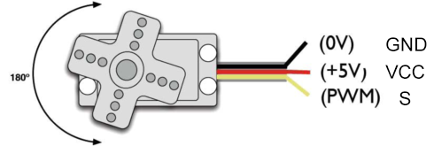
GND: Grounded(brown)
VCC: A red pin that connects to a +5v (3.3V) power
S: A orange signal pin that controlled via PWM signal
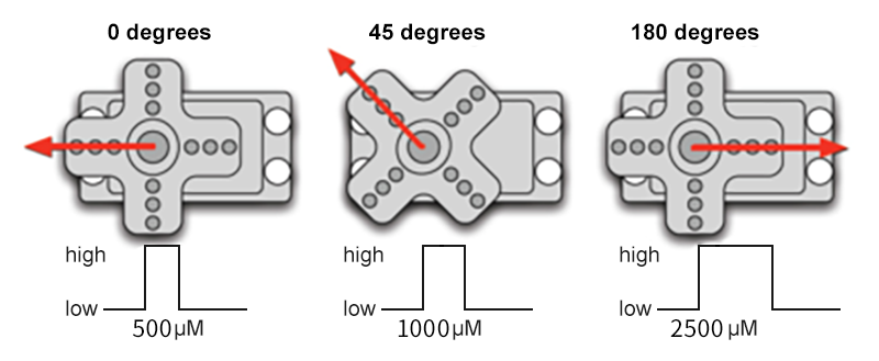
Control Principle: The rotation angle is controlled via duty cycle of PWM. Theoretically, standard PWM cycle is 20ms(50Hz), so pulse width should distribute within 1ms~2ms. However, the actual pulse width reaches 0.5ms~2.5ms, which corresponds to 0°~180°. Pay attention that, for the same signal, the rotation angle may vary from servo brands.
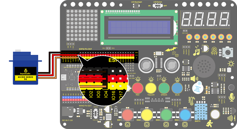
3. Wiring Diagram
4. Test Code
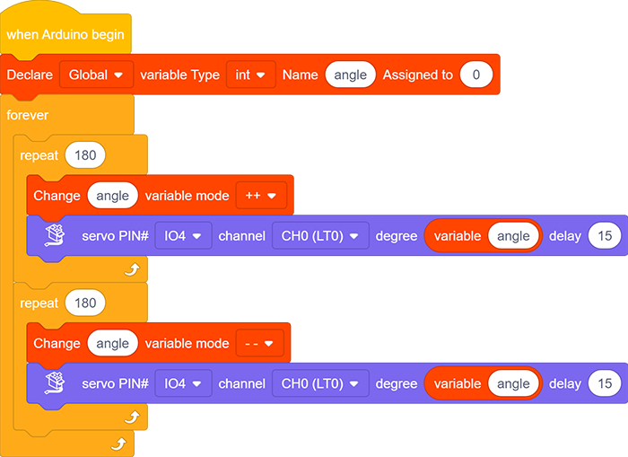
Drag the two basic blocks and put a “variable” block between them. Set the variable type to int, name to angle, and assign 0 as its initial value.

Servo gradually rotates from 0° to 180°:
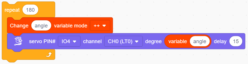
Add a repeat block and set the repeat times to 180(180 angles). Drag a “change variable” and a “servo” block and put them in the repeat one. Name the variable “angle” and select the mode “++”. Set Servo PIN to IO4 and degree to the named variable. Don’t forget to delay 15s.
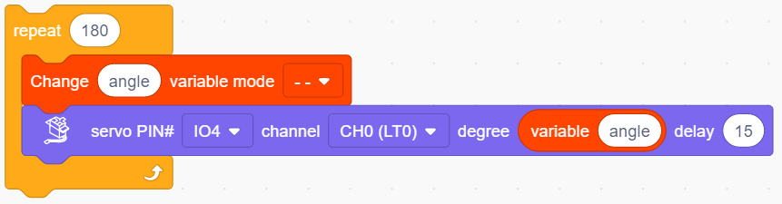
Servo gradually rotates from 180° to 0°: Repeat step 2, but set the variable mode to “- -”.
Complete Code:
5. Test Result
After connecting the wiring and uploading code, the servo starts to rotate from 0° to 180° and then from 180° to 0°.
6. Code Explanation
Set the values of Servo. Servo pin and rotation angle can be controlled by setting parameters on this block.

Read the current degree of the Servo.