Project 21 Sound Controlled LED
1. Description
Sound controlled LED is a device used to detect sound in a way that controls the brightness of LED, which is composed of a Arduino board and some components. It can connect to multiple sensors such as microphones. It converts sound to changing voltage signal to be received by Arduino to control the LED on and off.
2. Working Principle
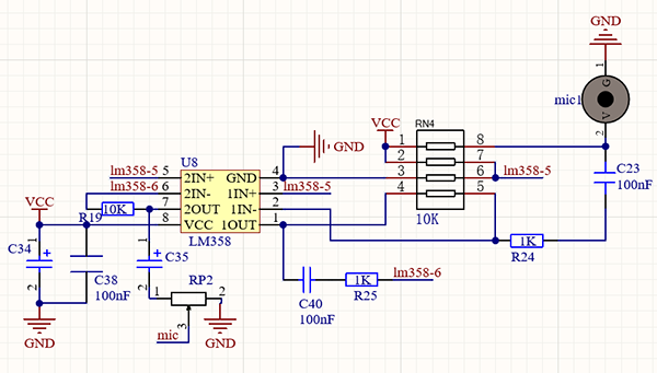
When detecting a sound, the electret film in microphone vibrates, which changes the capacitance and generates a subtle change of voltage.
Next, we make use of LM386 chip to build a proper circuit to amplify the detected sound up to 200 times, which can be adjusted by a potentiometer. Rotate it clockwise to enlarge the times.
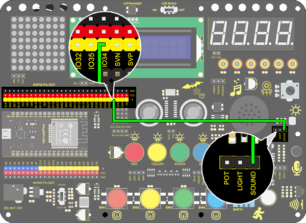
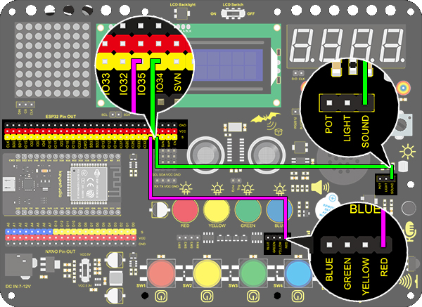
3. Wiring Diagram
4. Test Code
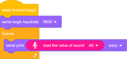
Find the “read the value” block in “Sound”, and print the read sound in the serial port. Construct blocks as follows. Pay attention that do not add a delay when using the sound sensor.
5. Test Result
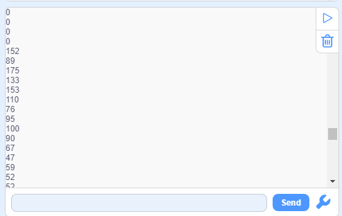
After connecting the wiring and uploading code, open serial monitor to set baud rate to 9600, the analog value will be displayed.
6. Expansion Code
The commonly seen corridor light is a kind of sound controlled light. Meanwhile, it also includes a photoresistor.
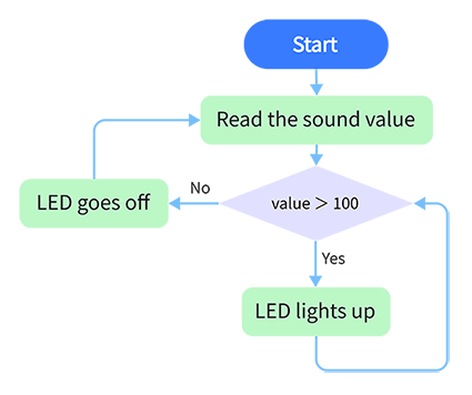
Differed from that, here we establish a model that an LED is only affected by sound. When the analog volume exceeds 100, LED lights up for 2s and then goes off.
Flow Chart:
Wiring Diagram:
Code:
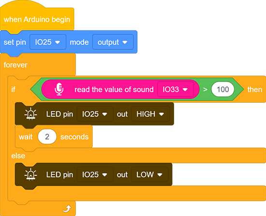
Drag two basic blocks.
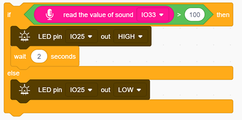
Drag an “if else” block, and fill the hexagon with a item>100 block. Set the value to “read the value of sound IO33”. If the condition is satisfied, LED outputs a HIGH level at pin IO25 with a delay of 2s; or else, it outputs a LOW level at the same pin without a delay.
Complete Code:
7. Code Explanation
Read the value of sound by setting the related pin.
 Project 22 Noise Meter
1. Description
Arduino noise meter embodies the sound signal to a series of dots, which are converted into patterns displayed on dot matrix.
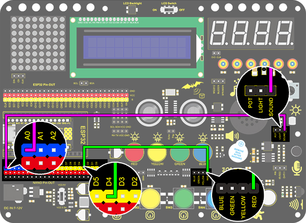
2. Wiring Diagram
3. Test Code
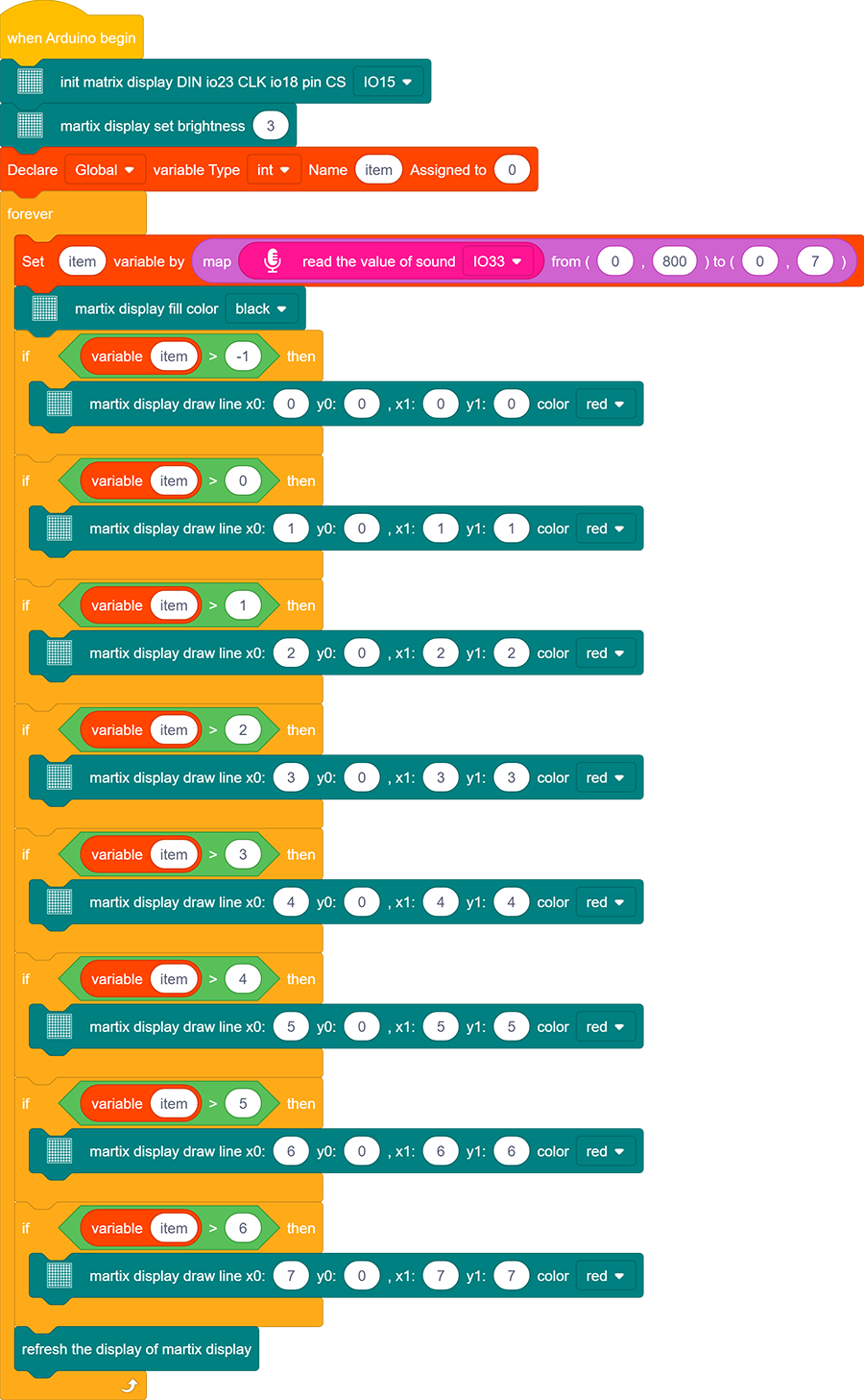
Drag the basic blocks and initialize the display. Set the pin CS to IO15 and brightness to 3. Then add a variable block and select int and name it as “item” with an initial assignment of 0.
Add a variable block and name it as “item”. Adopt a map function to convert the read sound value range from 0-4095 to 0-7, yet the hypothesis maximum value of sound is 800.

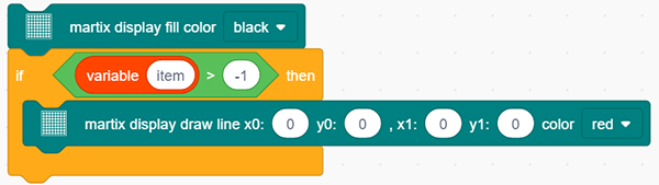
Clear the display.
Program a condition. If the variable item is greater than -1, the dot matrix displays (x0:0 y0:0 x1:1 y1:0) in color of red.
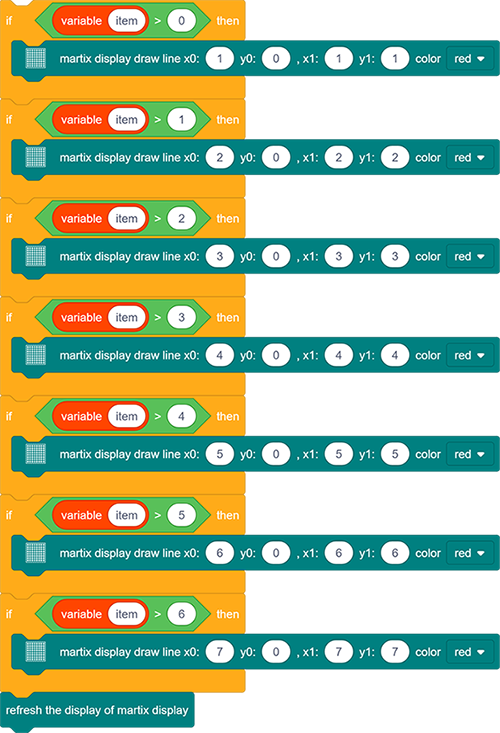
Repeat step 4, but the judgment is whether item is greater than 0. If so, dots at (x0:1 y0:0 x1:1 y1:1) will light up. By that analogy, build code blocks referring to the following coordinates.
Finally, refresh the display.
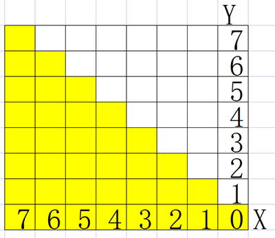
Reference Coordinates:
Complete Code:
4. Test Result
After connecting the wiring and uploading code, the noise level view is displayed on dot matrix, as shown below.