Project 22 Noise Meter
1. Description
Arduino noise meter embodies the sound signal to a series of dots, which are converted into patterns displayed on dot matrix.
2. Wiring Diagram
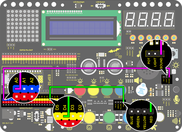
3. Test Code
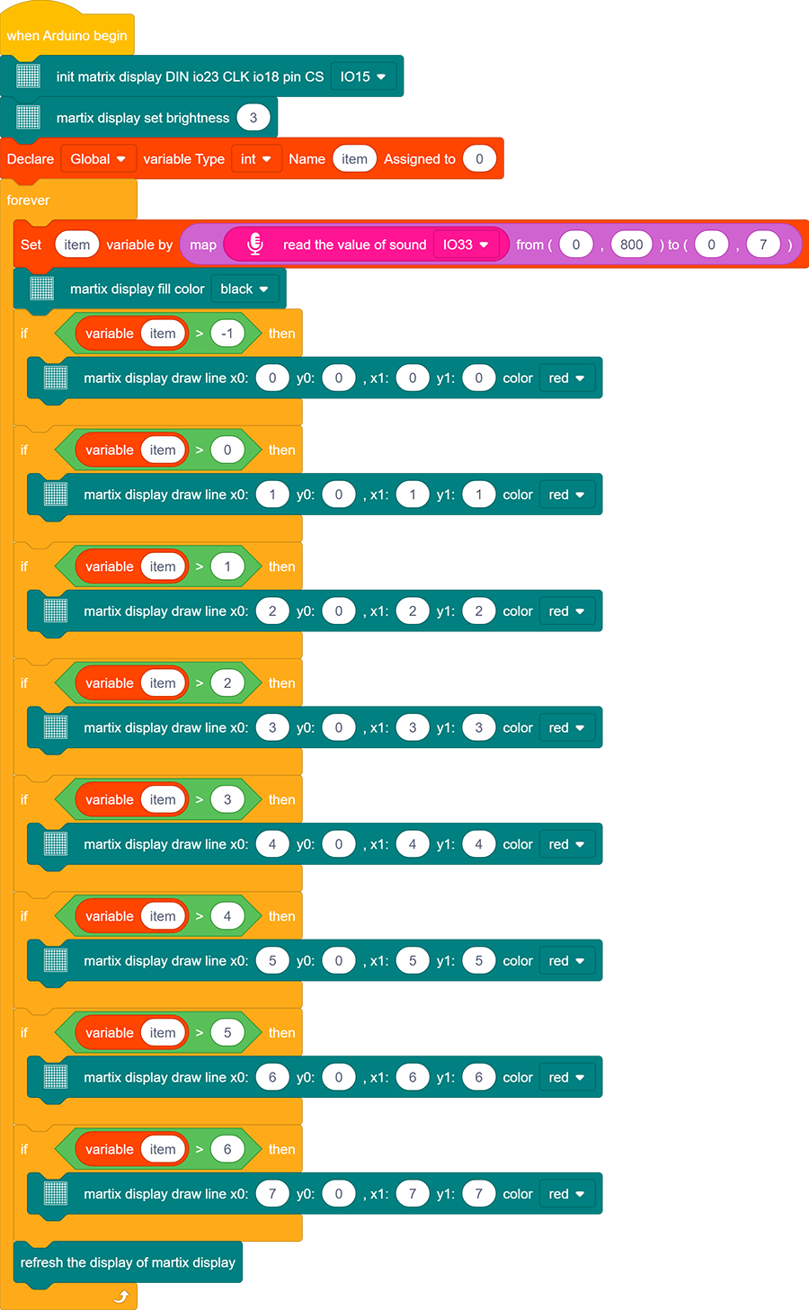
Drag the basic blocks and initialize the display. Set the pin CS to IO15 and brightness to 3. Then add a variable block and select int and name it as “item” with an initial assignment of 0.
Add a variable block and name it as “item”. Adopt a map function to convert the read sound value range from 0-4095 to 0-7, yet the hypothesis maximum value of sound is 800.

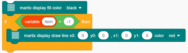
Clear the display.
Program a condition. If the variable item is greater than -1, the dot matrix displays (x0:0 y0:0 x1:1 y1:0) in color of red.
Repeat step 4, but the judgment is whether item is greater than 0. If so, dots at (x0:1 y0:0 x1:1 y1:1) will light up. By that analogy, build code blocks referring to the following coordinates.
Finally, refresh the display.
Reference Coordinates:
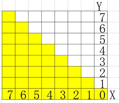
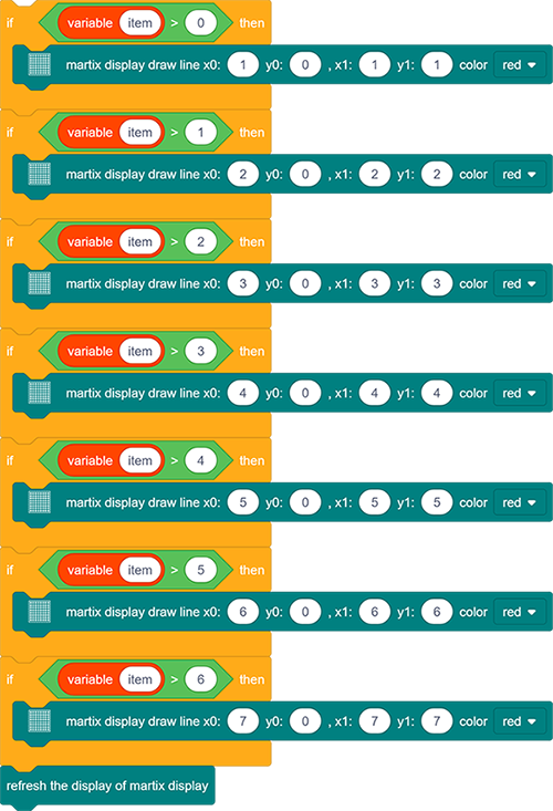
Complete Code:
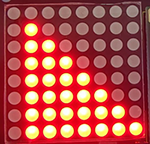
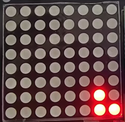
4. Test Result
After connecting the wiring and uploading code, the noise level view is displayed on dot matrix, as shown below.