Project 01: Small Lamp with Button
1. Overview
There are two programmable buttons on the front of the micro:bit board (A and B). We combine them with a red LED and a lamp card to build a small desk lamp. When the button A is pressed, the red LED lights up; when B is pressed, it goes off.
2. Components
|
|
|
|---|---|---|
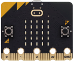
micro:bit board *1 |
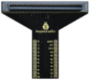
micro:bit T-type expansion board *1 |
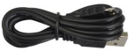
micro USB cable *1 |
|
|
|
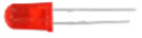
red LED *1 |
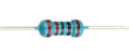
220Ω resistor *1 |
jump wire *2 |
|
|
|
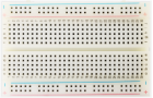
breadboard *1 |
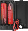
battery holder *1 |
lamp card *1 |

3. Components Knowledge
Buttons
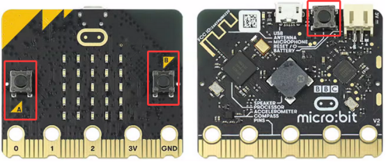
Buttons can control the circuit on and off. When a button is connected to a circuit, the circuit is opened when the button is not pressed; the circuit will be closed after pressing the button.
There are three buttons on the micro:bit board: a reset button on its back and two programmable buttons (A and B) on its front.
Resistors

A resistor is an electronic component that limits the current in a branch circuit. The resistance of a fixed resistor cannot be adjusted, while that of a potentiometer or a variable resistor can.
Here are two common circuit symbols for resistors. If you see these symbols in a circuit, they represent a resistor.

Ω is the unit of resistance, including Ω, KΩ, MΩ, etc. They can be expressed as: 1 MΩ=1000 KΩ, 1 KΩ =1000 Ω. In general, some resistances are marked on the surface.
When using a resistor, we first need to know its resistance. There are two ways: observe the color band on it, or measure its resistance by a multimeter. Obviously, the former one is more convenient and faster.
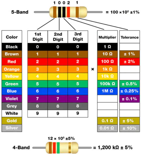
As shown in the resistor card, each color represents a number.

4-band and 5-band resistors are commonly used.
Often, when you get a resistor, you may find it difficult to decide where to start reading the color.
Therefore, you can observe the gap between the two bands at one end of it; if it is wider than any other band gap, read from the opposite end.
Note that the gap between the 4th and 5th bands (the 3rd and 4th) is relatively wide in a 5-band (4-band) resistor.
Let’s see how to read the resistance of a 5-band resistor, as shown below:
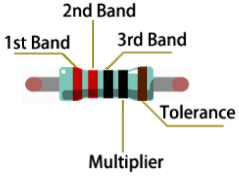
For this resistor, the resistance should be read from left to right. The value should be: 1st band 2nd band 3rd band x 10^multiplier(Ω), ±tolerance%.
Therefore, the resistance of this resistor is 2(red) 2(red) 0(black) × 10^0 (black)Ω = 220Ω, ±1%(brown). Learn more about resistor from Wiki.
LED
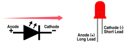
LED, fully called “light-emitting diode”, which is an electronic device made of semiconductor materials (silicon, selenium, germanium, etc.). It is polar, with a positive pole - the long pin connected to VCC (V or 3.3V or 5V or +), and a negative pole - the short pin connected to GND (G or-). The current flows from the positive to the negative, in a one-way flow.
Electronic and graphic symbol of LED:
LED in various sizes and colors:
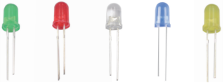
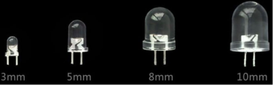
Red, yellow, blue, green and white are the most common colors of LED, which is same as their appearance colors. We rarely use transparent LED, and the light emitted may not be white. There are four sizes of LED: 3mm, 5mm(most common), 8mm and 10mm.
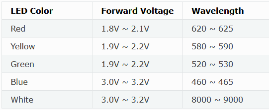
Forward voltage needs to be used when the LED is on. It is a very important parameter to know when using an LED, as it determines how much power you use and how large the current limiting resistor should be. For most red, yellow, orange and light green LED, they typically use a voltage between 1.9V and 2.1V.
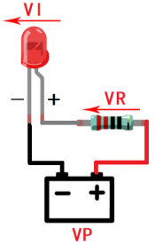
According to Ohm’s law, the current through the circuit decreases as the resistance increases, causing the LED to dim.
I = (VP-Vl)/R
In order to make the LED safe and have the right brightness, how much resistance should we use in the circuit?
For 99% of 5mm LED, the recommended current is 20mA, which can be seen from the conditions column in its data sheet:
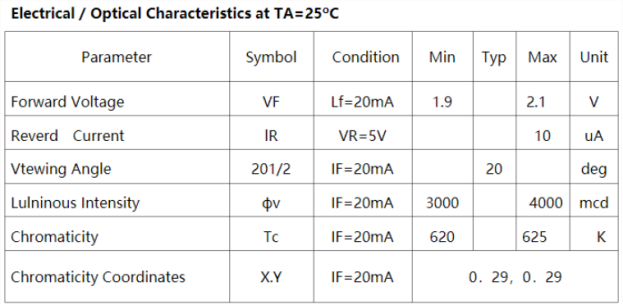
Now convert the above formula to the following:
R = (VP-Vl)/I
If VP = 5V, Vl (forward voltage) = 2V, and I = 20mA, we can tell R is 150Ω. Therefore, we can make the LED brighter by reducing the resistance, but the resistance should not be below 150Ω (this value may not be accurate because the provided LED varies).
The forward voltage and wavelength of different colors of LED are shown below for your reference:
Do not connect a resistor with very low resistance directly to the two poles of the power supply, or the electronic components may be damaged due to excessive current. Resistors are non-polar.
Breadboard
Before completing any circuit, a breadboard is used for quickly designing and testing circuits. There are many holes on a breadboard that can be inserted with circuit components (say, resistors). A typical breadboard is shown below:
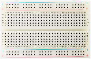
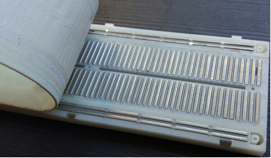
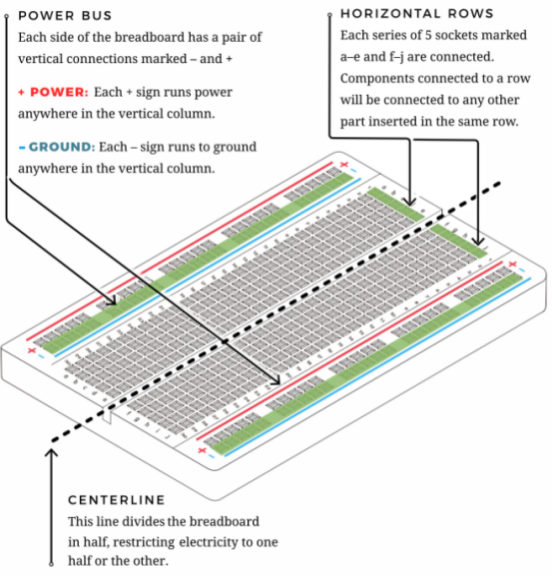
A breadboard has many metal strips under it to connect to the holes at the top. They are arranged as shown below.
Note that the top and bottom holes are horizontally connected, while the rest of the holes are vertically connected.
The first two rows(top) and the last two(bottom) of the breadboard are used for the positive(+) and negative(-) poles of the power supply, respectively. The conductive layout diagram is shown below:
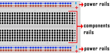
When connecting DIP(Dual In-line Packages) components, such as integrated circuits, microcontrollers, chips, etc., the groove isolates the two parts. Therefore, DIP components can be connected as shown below:
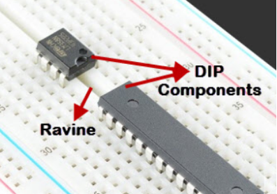
Jump wire and DuPont wire
Jump wires and DuPont wires connect two terminals. There are various types of them, but here we focus on those used in breadboard. They transmit electrical signals from anywhere on the breadboard to the input/output pins of a microcontroller.
When using, insert “two pins” of the wires into the breadboard without soldering. Several sets of parallel boards are arranged under the surface of the breadboard, so wires only need to be inserted in specific holes in a particular prototype.
There are three types of DuPont wires: F-F, M-M and M-F. On the wire, the pin is called male end(M), while the hole is female(F).

More than one type can be used in a project. Although the colors of wires are different, they serve the same purpose. Colors are used to distinguish circuits.
4. Wiring Diagram
Note: the micro:bit board needs to be inserted into the T-type expansion board as shown below. The micro:bit board LED matrix should be on the same side with the logo of the expansion board.
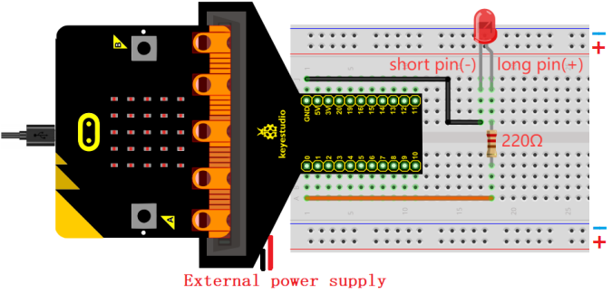
The board control pin of LED is P0 (the pin of T-type expansion board is digital 0).
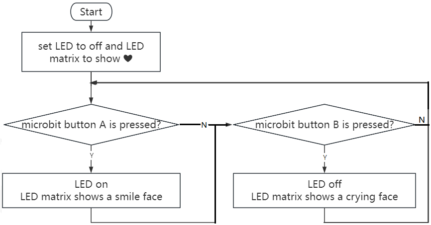
5. Code Flow
6. Test Code
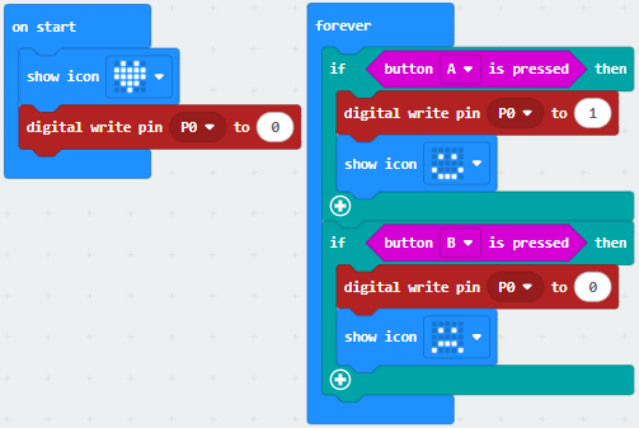
The code file is provided in folder Project 01:Small Lamp with Button, file Project-01-Small-Lamp-with-Button.hex.

Load code blocks:
7. Test Result
For Windows 10 App, click “Download” . For browsers, send the downloaded “.hex” file to the micro:bit board.
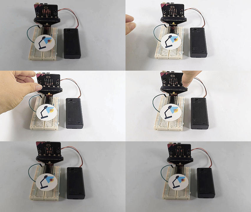
After downloading the code to the board, 5x5 LED matrix shows  icon. Press button A, and 5x5 LED matrix shows
  icon, LED turns on. Press button B, 5x5 LED matrix shows
  icon, LED goes off. Does it look like a mini lamp?
ATTENTION: If the wiring is correct but you cannot see the results, press the reset button on the back of the board.
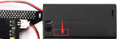
When powering on via external power supply, turn the DIP switch to ON.