Project 03: Ranging Bat
1. Overview
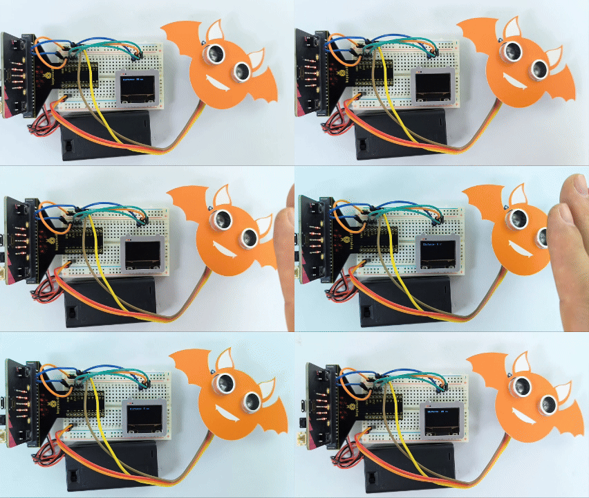
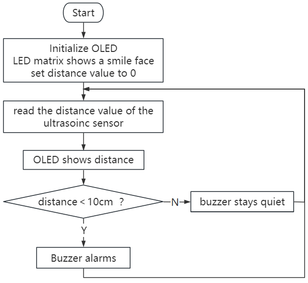
Based on an ultrasonic sensor, the ranging bat detects the distance of obstacles and displays it in real time on an OLED. When it is less than 10cm, the speaker alarms.
2. Components
|
|
|
|---|---|---|
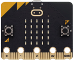
micro:bit board *1 |
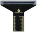
micro:bit T-type expansion board *1 |
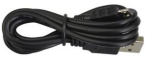
micro USB cable *1 |
|
|
|
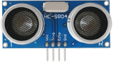
ultrasonic sensor *1 |
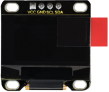
OLED module *1 |
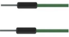
DuPont wires |
|
|
|
breadboard *1 |
jump wires |
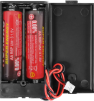
battery holder *1 |
|
|
|
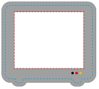
bat card *1 |
OLED card *1 |

3. Components Knowledge
ultrasonic sensor
Ultrasonic waves bounce back when they hit an obstacle. We measure the distance by calculating the time interval between sending and receiving the waves. Since the propagation speed of sound in air is a constant v=340m/s, we calculate the distance between the sensor and the obstacle: s=vt/2.
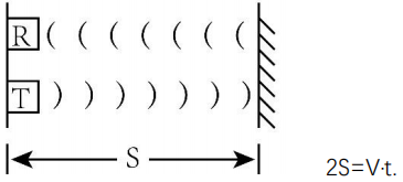
The HC-SR04 ultrasonic module integrates a transmitter and receiver. The former converts electrical signals (electric energy) into high frequency (beyond human hearing) sound waves (mechanical energy), while the latter does the opposite.
The schematic diagram of the HC SR04:
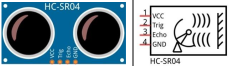
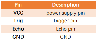
Pin definition:
Parameters:
Operating voltage: 5V
Operating current: 12mA
Minimum measuring distance: 2cm
Maximum measuring distance: 200cm
Working principle:
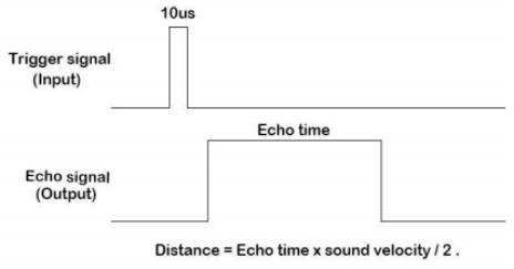
A high level pulse lasting at least 10us is output on the Trig pin, and the module starts transmitting ultrasonic waves. At the same time, the Echo pin is pulled up. When the module receives an ultrasonic wave back when it encounters an obstacle, the Echo pin will be pulled down. The duration of the high level of the Echo pin is the total time of wave from sending to receiving: s=vt/2.
OLED module
OLED technology features rich color performance, high contrast and wide perspective, providing clear and vivid pictures, especially outstanding in black.
Each pixel of the OLED display emits light itself without backlight, so it consumes relatively low power. With small size, high resolution and low power consumption, the 0.9-inch OLED display is very suitable for wearable devices.
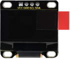
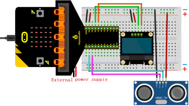
In this project, the OLED display module connects the SDA interface to pin P20 and SCL to pin P19.
Parameters:
Operating voltage: DC 3.3V-5V
Operating current: 30mA
Interface: Pin ports with a spacing of 2.54mm
Communication mode: I2C
Internal driver chip: SSD1306
Resolution: 128*64
Viewing Angle: greater than 150°
4. Wiring Diagram
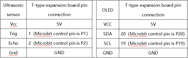
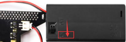
When using the OLED display and ultrasonic sensor, we must connect an external power supply and turn the DIP switch to ON.
5. Code Flow
6. Test Code
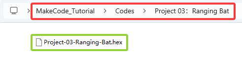
The code file is provided in folder Project 03:Ranging Bat, file Project-03-Ranging-Bat.hex.
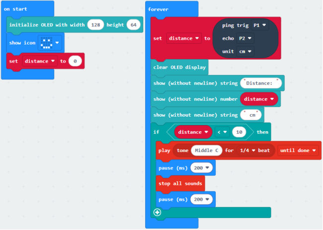
Load code blocks: The threshold in the condition 10 can be modified according to actual conditions.
7. Test Result
For Windows 10 App, click “Download” . For browsers, send the downloaded “.hex” file to the micro:bit board.
After downloading the code to the board, power on via external power supply and turn the DIP switch to ON, and the OLED displays the distance between the ultrasonic sensor and the obstacle in real time. When the distance value is less than 10cm, the speaker on micro:bit board alarms.
ATTENTION: If the wiring is correct but you cannot see the results, press the reset button on the back of the board.