Project 05: Car Dial
1. Overview
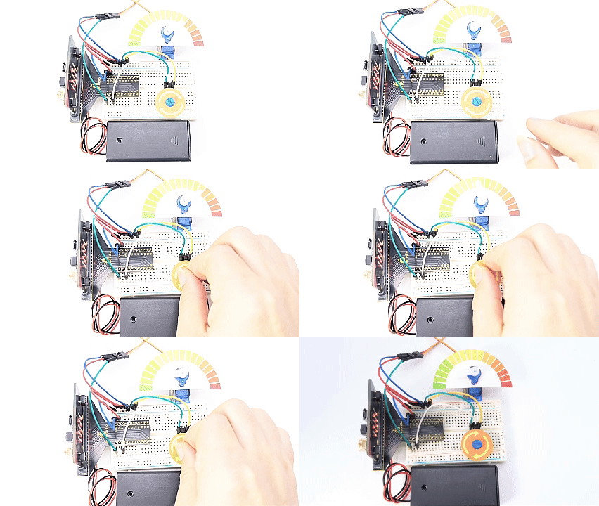
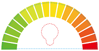
In this project, we combine an adjustable potentiometer, a servo and a beautiful dial card to make a simple car dial model.
2. Components
|
|
|
|---|---|---|
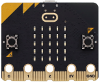
micro:bit board *1 |
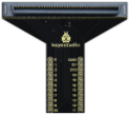
micro:bit T-type expansion board *1 |
micro USB cable *1 |
|
|
|
potentiometer *1 |
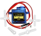
servo *1 |
jump wires |
|
|
|
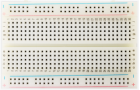
breadboard *1 |
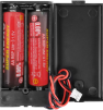
battery holder *1 |
potentiometer card *1 |
|
||
car dial card*1 |

3. Components Knowledge
potentiometer
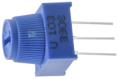
A potentiometer is also a resistor element with three contacts, whose resistance value can be adjusted according to some regularity.
They come in all shapes, sizes and values, but they all have the followings in common:
① Three terminals (or connection points).
② A movable knob or slider that can change the resistance between the intermediate terminal and any external terminal.
③ As the knob is moved, the resistance between the intermediate terminal and any external terminal varies from 0Ω to its maximum.
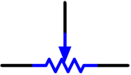
The circuit symbol of potentiometer:
(1). As a voltage divider
The potentiometer is a continuously adjustable resistor. When you rotate its slider, the moving contact slides across the resistor. At this point, a voltage can be output according to the voltage applied to potentiometer and the angle or stroke of rotation of the movable slider.
(2). As a variable resistor
When potentiometer is used as a variable resistor, connect its intermediate terminal to one of two additional terminals in the circuit. In this way, you can obtain a steady and continuously varying resistance value within the range of it.
(3). As a current controller
When it is used as a current controller, the moving contact must be connected as one of the output terminals.
4. Wiring Diagram
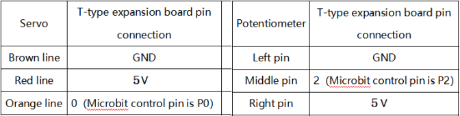
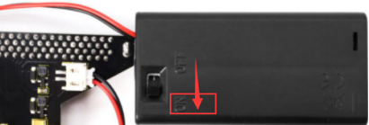
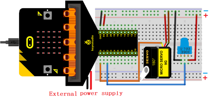
When using the servo, we must connect an external power supply and turn the DIP switch to ON.
5. Code Flow
6. Test Code
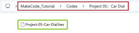
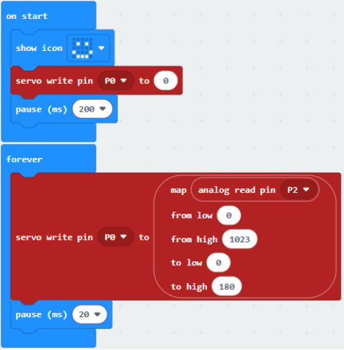
The code file is provided in folder Project 05:Car Dial, file Project-05-Car-Dial.hex.
Load code blocks:
7. Test Result
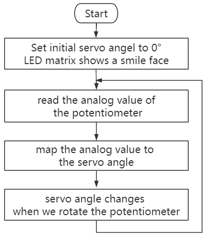
After downloading the code to the board, rotate the knob on potentiometer and the servo moves the pointer on the dial.
ATTENTION: If the wiring is correct but you cannot see the results, press the reset button on the back of the board.