Project 08: Anti-theft Alarm
1. Overview
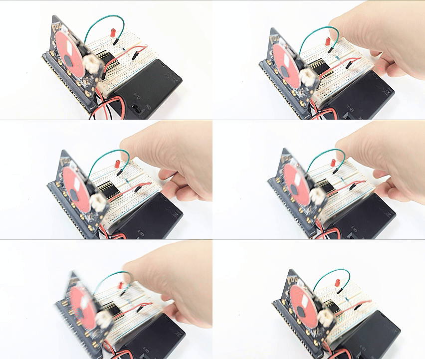
When the smart anti-theft alarm detects that the anti-theft box has been moved, the speaker on the micro:bit board will alarm and the red LED will flash.
2. Components
|
|
|
|---|---|---|
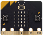
micro:bit board *1 |
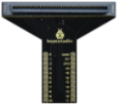
micro:bit T-type expansion board *1 |
micro USB cable *1 |
|
|
|
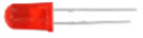
red LED *1 |
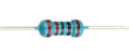
220Ω resistor *1 |
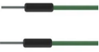
jump wire *2 |
|
|
|
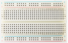
breadboard *1 |
battery holder *1 |
alarm card *1 |


3. Components Knowledge
Accelerometer
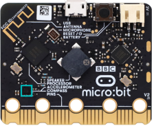
The micro:bit board boasts a built-in LSM303AGR acceleration sensor (we called accelerometer) which includes standard, fast, plus and high-speed mode (100 kHz, 400 kHz, 1 MHz and 3.4 MHz) of I2C serial bus interface and SPI serial standard interface for external communication, with resolution of 8/10/12 bits and range of ±2g, ±4g, or ±8g.
When the micro:bit board is at rest or in uniform motion, the accelerometer only detects the acceleration of gravity. If it is slightly swung, the detected acceleration is much less than the that of gravity, so the difference can be ignored. Therefore, we mainly detect the change of gravitational acceleration on x, y, and z axes.
4. Wiring Diagram
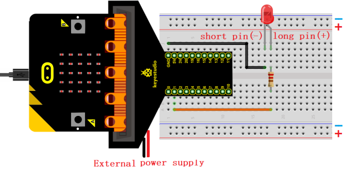
The board control pin of LED is P1 (the pin of T-type expansion board is digital 1).
5. Code Flow
6. Test Code
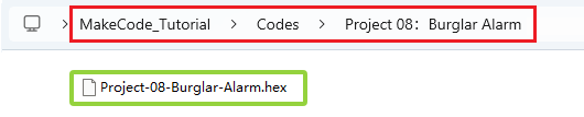
The code file is provided in folder Project 08:Burglar Alarm, file Project-08-Burglar-Alarm.hex.
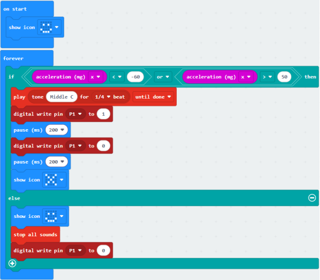
Load code blocks:
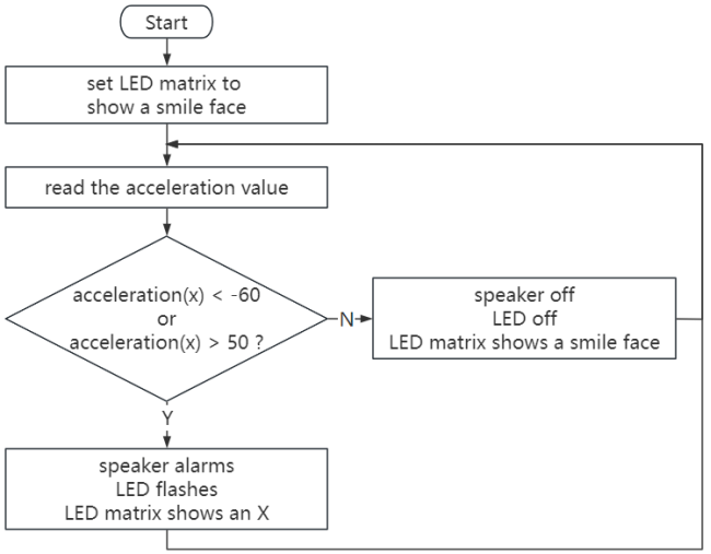
After importing the code, if the buzzer keeps sounding even though the breadboard is not moved; it may be caused by geographical factors. You can modify the threshold in the condition -60 and 50 according to actual conditions.
7. Test Result
After downloading the code to the board, move the breadboard. If the acceleration value x<-60 or x>50, the speaker on the board alarms and the LED flashes, and the micro:bit LED matrix shows  . Otherwise, the speaker makes no sound and LED is off, and the micro:bit LED matrix shows
  .
.
ATTENTION: If the wiring is correct but you cannot see the results, press the reset button on the back of the board.