Project 02: Traffic Lights
1. Overview
In this project, we adopt three LEDs( red, yellow and green), a speaker on micro:bit board and 5x5 LED matrix to make a model of traffic lights.
2. Components
|
|
|
|---|---|---|
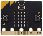
micro:bit board *1 |
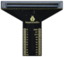
micro:bit T-type expansion board *1 |
micro USB cable *1 |
|
|
|
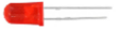
red LED *1 |
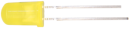
yellow LED *1 |
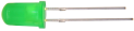
green LED *1 |
|
|
|
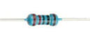
220Ω resistor *3 |
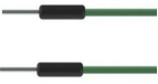
jump wires |
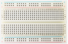
breadboard *1 |
|
|
|
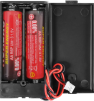
battery holder *1 |
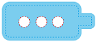
traffic lights card *1 |
3. Components Knowledge
Speaker
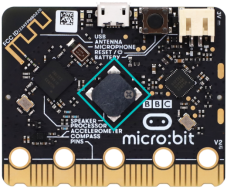
Micro: bit comes with a speaker, which makes it easy to make sound in your project.
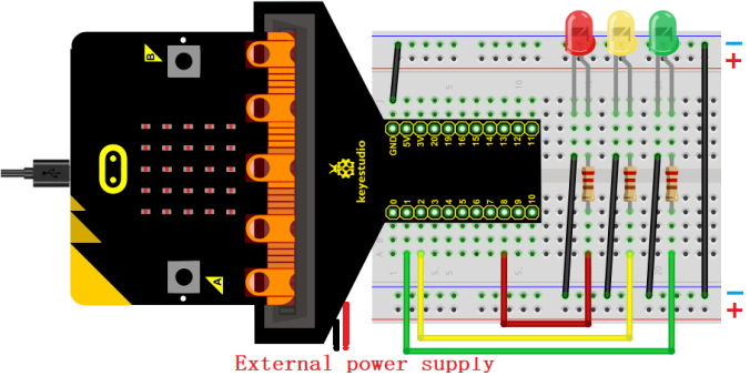
4. Wiring Diagram
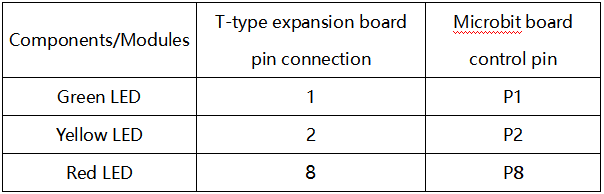
Note: the micro:bit board needs to be inserted into the T-type expansion board as shown below. The micro:bit board LED matrix should be on the same side with the logo of the expansion board.
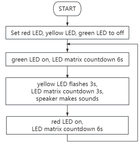
5. Code Flow
6. Test Code
The code file is provided in folder Project 02:Traffic Lights, file Project-02-Traffic-Lights.py.

Complete code:
'''
Function: traffic lights with countdowns and buzzes
Compiling IDE: MU 1.2.0
Author: https://docs.keyestudio.com
'''
# import microbit related libraries
from microbit import *

pin1.write_digital(0) # set P1 pin to low
pin2.write_digital(0) # set P2 pin to low
pin8.write_digital(0) # set P8 pin to low

import music # import music libraries

while True:
   pin1.write_digital(1)  # P1 pin to high
   display.show('6')  # LED matrixs shows 6
   sleep(1000)        # delay 1s
   display.show('5')
   sleep(1000)
   display.show('4')
   sleep(1000)
   display.show('3')
   sleep(1000)
   display.show('2')
   sleep(1000)
   display.show('1')
   sleep(1000)
   display.show('0')
   sleep(1000)
   pin1.write_digital(0)
   pin2.write_digital(1)
   music.play("C4:4")    # speaker plays C4 tone
   display.show('2')
   sleep(500)
   pin2.write_digital(0)
   music.reset()         # no tone
   sleep(500)
   pin2.write_digital(1)
   music.play("C4:4")
   display.show('1')
   sleep(500)
   pin2.write_digital(0)
   music.reset()
   sleep(500)
   pin2.write_digital(1)
   music.play("C4:4")
   display.show('0')
   sleep(500)
   pin2.write_digital(0)
   music.reset()
   sleep(500)
   pin8.write_digital(1)
   display.show('6')
   sleep(1000)
   display.show('5')
   sleep(1000)
   display.show('4')
   sleep(1000)
   display.show('3')
   sleep(1000)
   display.show('2')
   sleep(1000)
   display.show('1')
   sleep(1000)
   display.show('0')
   sleep(1000)
   pin8.write_digital(0)
7. Test Result
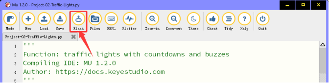
Click “Flash” to load the code to the micro:bit board.
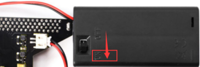
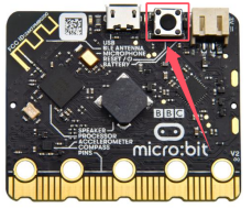
After downloading the code to the board, power on via micro USB cable or external power supply(turn the DIP switch to ON), and press the reset button on the board.
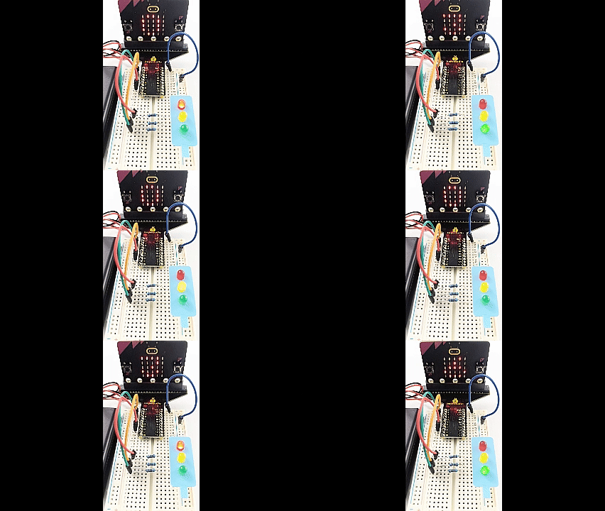
The green LED turns on and the 5×5 LED matrix counts down 6 seconds. After the green LED is off, the yellow LED flashes and the matrix counts down 3s with speaker sounding. At last, the red LED is on with a countdown of 6s. These actions repeat.
ATTENTION: If the wiring is correct but you cannot see the results, press the reset button on the back of the board.
When powering on via external power supply, turn the DIP switch to ON.