Project 04: Smart Paeking
1. Overview
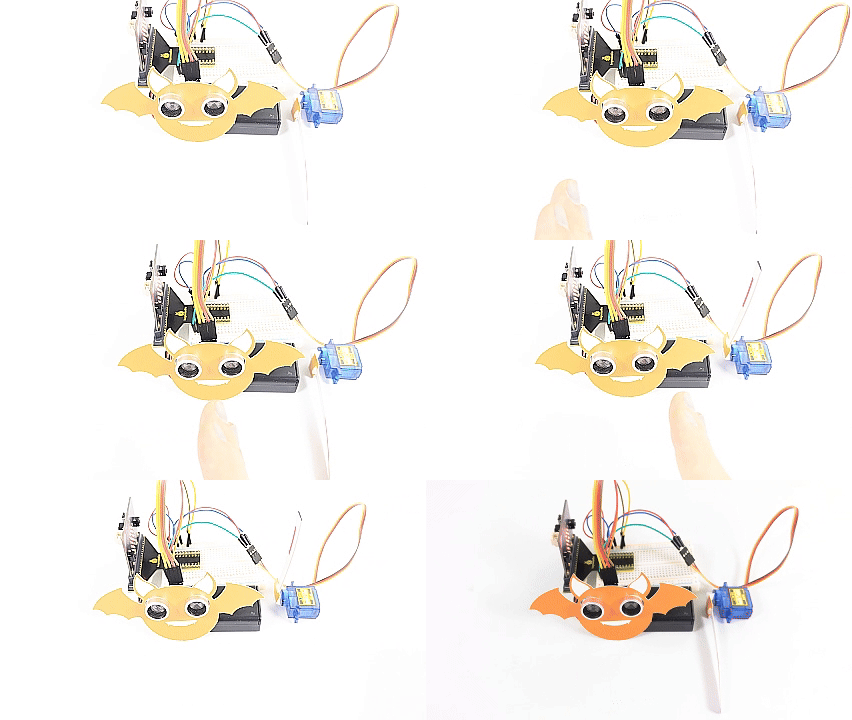
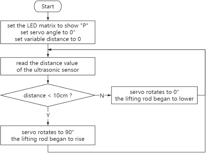
Smart parking lots are everywhere. Can we also create a smart parking lot? Of course. We can use ultrasonic sensor to detect if there are vehicles ahead. When a vehicle (or thing) is detected approaching, we control servo to raise the lift rod; If it is detected to be moving away, the servo will lower the lift rod.
2. Components
|
|
|
|---|---|---|
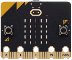
micro:bit board *1 |
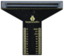
micro:bit T-type expansion board *1 |
micro USB cable *1 |
|
|
|
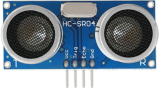
ultrasonic sensor *1 |
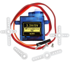
servo *1 |
DuPont wires |
|
|
|
breadboard *1 |
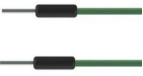
jump wires |
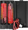
battery holder *1 |
|
|
|
bat card *1 |
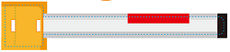
lift rod card *1 |

3. Components Knowledge
Servo
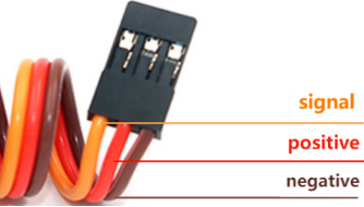
Servo is a position driver. We can use servo to control the exact position or output high torque. Usually, it is used in robots, remote control cars, and even aircraft models. There are many specifications, but all servos comes with three wires: signal(orange), positive(red) and negative(brown). The color will vary from servo brands.
Internal structure diagram:
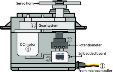
① Signal: receives control signals from the microcontroller;
② potentiometer: The position of the output shaft can be measured, which belongs to the feedback part of the whole servo;
③ Internal controller: The embedded board processes signals from external control, drives the motor and feedback position signals, which is the core of the whole servo;
④ DC motor: It is as an actuator to output speed, torque, position;
⑤ Transmission / servo mechanism: The mechanism zooms in the stroke output by the motor to the final output angle according to a certain transmission ratio.
Drive the servo
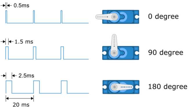
Send PWM signals to the servo signal line to control its output. The duty cycle of PWM directly determines the position of the output shaft. The period is usually 20 milliseconds and is typically set to generate pulses at a frequency of 50Hz.
For example (180° servo):
When we send a pulse width of 1.5 milliseconds (ms) to the 180° servo, the output shaft of the servo will move to the middle position (90 degrees);
If the pulse width is 0.5ms, the output shaft will move to 0 degree;
If the pulse width is 2.5ms, the output shaft will move to 180 degree;
Parameters:
Operating voltage: DC 3.3V~5V
Operating temperature: -10°C ~ +50°C
Dimensions: 32.25mm x 12.25mm x 30.42mm
Interface: 3pin interface with a spacing of 2.54mm
4. Wiring Diagram
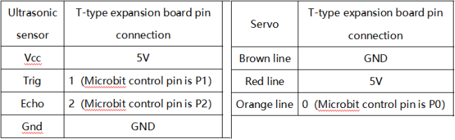
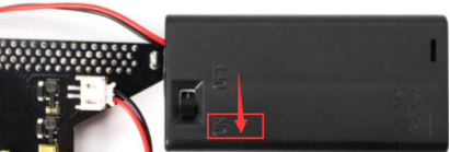
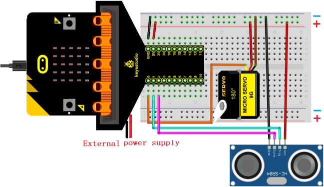
When using the ultrasonic sensor and servo, we must connect an external power supply and turn the DIP switch to ON.
5. Code Flow
6. Test Code
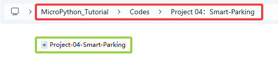
The code file is provided in folder Project 04:Smart-Parking, file Project-04-Smart-Parking.py.
Complete code: The threshold in the condition 10 can be modified according to actual conditions.
'''
Function: smart parking
Compiling IDE: MU 1.2.0
Author: https://docs.keyestudio.com
'''
# import related libraries
from microbit import *
import ustruct
import machine
from time import sleep_us

distance = 0              # set variable distance initial value to 0
lastEchoDuration = 0      # set variable lastEchoDuration initial value to 0

val = Image("09990:""09090:""09990:""09000:""09000")  # set iamge
display.show(val)        # LED matrix shows image
pin0.write_analog(25.6)    # set P0 pin analog to 25.6, servo angle to 0°
sleep(200)

while True:
    pin0.set_analog_period(20) # set servo frequency
    # Ultrasonic sensor sends and receives signals
    pin1.write_digital(0)
    sleep_us(2)
    pin1.write_digital(1)
    sleep_us(15)
    pin1.write_digital(0)

    # measure the time interval between "when rising edge detected from the pin2" and "until the pin becomes low again"
    # unit is μs. Assign the interval to variable t.
    t = machine.time_pulse_us(pin2, 1, 35000)

    # a conditional statement, used to check whether the values of two variables t and lastechoduration satisfy specific conditions.
    # If both conditions are met, the block of code under the condition statement is executed.
    if (t <= 0 and lastEchoDuration >= 0):
        t = lastEchoDuration   # variable t = variable lastechoduration
    else:
        lastEchoDuration = t
    distance = int(t * 0.017)  # calculate distance
    if distance < 10:          # if distance < 10cm
       pin0.write_analog(77)   # servo rotate to 90°
       sleep(2000)
    else:  # or
       sleep(2000)
       pin0.write_analog(25.6)
       sleep(2000)
7. Test Result
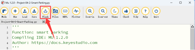
Click “Flash” to load the code to the micro:bit board.
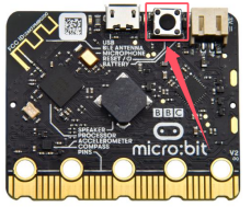
After downloading the code to the board, power on via micro USB cable or external power supply(turn the DIP switch to ON), and press the reset button on the board.
When the ultrasonic sensor detect a vehicle (or thing) approaching, the servo controls the lift rod to raise; If the sensor detects it moving away, the servo will lower the lift rod.
ATTENTION: If the wiring is correct but you cannot see the results, press the reset button on the back of the board.