Project 1 the application of L298N motor driver board
For the instruction for L298N driver board please refer to (L298N dual-H bridge DC motor driver board manual). Some of you still don’t know how to control dual DC motor. Here are the details.
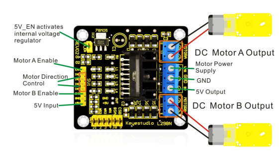
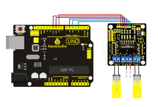
For the VMS driver part, power supply can be external power source, generally about 9V. For the logic part, power supply can be from the board internally; with terminals in suspense state, they can also be connected to +5V to +7V power. The three pins between each terminal are used to control the dual DC motor. EA and EB are connected to Arduino PWM interface for motor speed regulation. I1, I2, I3, I2 interface, connected to Arduino digital interfaces, are used for controlling the motor going forward, backward, steering and braking. Up until now, the preparatory work is completed. You can begin writing the program now. Here, the program for your reference includes car going straight, backward, turning left, turning right, and braking.
Program
Code 1
int pinI1=5;// define pin  I1
int pinI2=6;// define pin I2
int speedpin=3;// define  pin EA(PWM speed regulation)
int pinI3=10;// define pin I3
int pinI4=11;// define pin I4
int speedpin1=9;// define  pin EB(PWM speed regulation)

void setup()
{
    pinMode(pinI1,OUTPUT);
    pinMode(pinI2,OUTPUT);
    pinMode(speedpin,OUTPUT);
    pinMode(pinI3,OUTPUT);
    pinMode(pinI4,OUTPUT);
    pinMode(speedpin1,OUTPUT);
}

void loop()
{
    // going straight
    analogWrite(speedpin,100);// input analog value to set the speed
    analogWrite(speedpin1,100);
    digitalWrite(pinI4,LOW);// make the DC motor turn(right) anti-clockwise
    digitalWrite(pinI3,HIGH);
    digitalWrite(pinI1,LOW);// make the DC motor turn(left) clockwise
    digitalWrite(pinI2,HIGH);
    delay(2000);
    // going backwards
    analogWrite(speedpin,100);// input analog value to set the speed
    analogWrite(speedpin1,100);
    digitalWrite(pinI4,HIGH);// make the DC motor turn(right) clockwise
    digitalWrite(pinI3,LOW);
    digitalWrite(pinI1,HIGH);//make the DC motor turn(left) anti-clockwise
    digitalWrite(pinI2,LOW);
    delay(2000);
    // turning left
    analogWrite(speedpin,60);// input analog value to set the speed
    analogWrite(speedpin1,60);
    digitalWrite(pinI4,LOW);// make the DC motor turn(right) anti-clockwise
    digitalWrite(pinI3,HIGH);
    digitalWrite(pinI1,HIGH);//make the DC motor turn(left) anti-clockwise
    digitalWrite(pinI2,LOW);
    delay(2000);
    // turning right
    analogWrite(speedpin,60);//input analog value to set the speed
    analogWrite(speedpin1,60);
    digitalWrite(pinI4,HIGH);//make the DC motor turn(right) clockwise
    digitalWrite(pinI3,LOW);
    digitalWrite(pinI1,LOW);//make the DC motor turn(left) clockwise
    digitalWrite(pinI2,HIGH);
    delay(2000);
    // braking
    digitalWrite(pinI4,HIGH);// make the DC motor brake(right)
    digitalWrite(pinI3,HIGH);
    digitalWrite(pinI1,HIGH);//make the DC motor brake(left)
    digitalWrite(pinI2,HIGH);
    delay(2000);
}
Note: in the program, there can be other ways to make the motor turning left or right. You can try it out yourself.