Project 2 Line tracking smart car
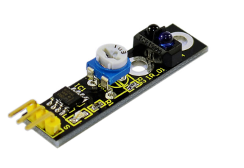
Line tracking principle: the working principle of the TCRT5000 infrared double tube is to use the infrared’s different reflectivity of different color, and convert the strength of the reflected signal into current signal. For black and white line tracking module, it’s high level signal when detecting black line, low level when detecting white line. Detect height is 0-3cm.
Note: you can use a knob potentiometer in the circuit to adjust the sensitivity of this tracking module. TCRT5000 infrared double tube is widely applied in robot design, and industrial manufacture. It can be used for black and white line tracking robot and industrial counting sensors.
1.Usage
For the sensor, there are 3 pins, namely GND, VCC, OUT. VCC and GND are for power supply. OUT is for signal output.
When it detects an object, the signal end outputs low level; when there is no object detected, the signal end outputs high level.
By judging whether the signal output is 0 or 1, it can know whether the object exists.
2.Performance parameter
Detection distance: about 2cm for white paper floor. Different distance depends on the color difference, farthest for white color.
Power supply voltage: 2.5V to 12V, no more than 12V. (note: it is better to use low voltage power supply, high power supply voltage will result in shorter service life of the sensor. 5V power supply is preferred.)
Working current: 18~20ma when the supply voltage is 5V. After many tests, when the working current is 18~20ma, the sensor is at its best performance in anti-jamming capability.
When it detects an object, the signal end outputs low level; when there is no object detected, the signal end outputs high level.
The sensor outputs TTL level; can be directly connected to the IO port of 3.3V or 5V MCU.
3.Black or white line detecting principle
For color black, it has characteristic of low reflectivity to light. When the surface color is not black, most of the red light the sensor sends will be reflected. The sensor outputs low level 0.
If there is black line on a surface, when the sensor is on it, color black has low reflectivity; reflected infrared light is not enough to reach the sensor action level, so the sensor output is still l.
To detect the black line, we only need a MCU to determine whether the sensor output is 0 or 1.
Detecting principle of white line is the same with black line. When white line is detected, the color surrounding the white line is close to black. We then adjust the adjustable resistor of the infrared sensor; lower the sensitivity until the surrounding color cannot be detected. The sensor can then detect the white line.
4.Test program
Code 2
int inputpin=7;// definedigital pin 7 as detection port
int val;// define variable

void setup()
{
    pinMode(inputpin,INPUT);// set digital pin 7 as output
    Serial.begin(9600);// set baud rate at 9600 for the serial port
}

void loop()
{
    val=digitalRead(inputpin);// read the value of the digital port
    Serial.println(val);// output the value of the digital port
}
5.Line tracking smart car
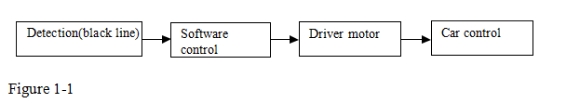
After some basic knowledge of line tracking module, let’s make our own line tracking smart car. This design of line tracking car system is base on Arduino . It includes software and hardware design. The controller unit of the car is Arduino UNO, using infrared photoelectric sensor to detect the black track and feedback the information to the Arduino board.
Arduino board will have analysis of the acquired information, timely control the driver motor to adjust the moving direction of the car. So the car can drive automatically along the black track, realizing the line tracking function. the system design is as below figure 1-1.
6.Car tracking principle
Here, tracking means the car will move along the black line on the white floor. Because the black line and the white floor has different reflection coefficient, the track can be determine by the strength of the reflected light. Usually, it adopts the method of infrared detection. That is to use infrared ray’s feature of reflection over different color.
When the car is driving, it will continually emit infrared ray to the ground. When the infrared ray encounters the floor made of white paper. It will be reflected. The reflected ray will be received by the receiver of the car. If it encounters the black track, infrared ray will be absorbed so the receiver won’t receive infrared ray. The microcontroller will determine the location of the black line and the moving direction of the car. Note that the detection rage of the infrared detector is limited.
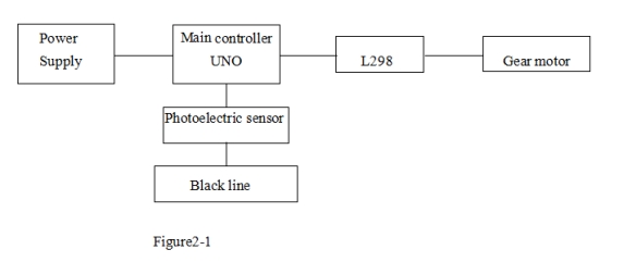
The control system of the line tracking car consists of a main control circuit module, power supply module, infrared detecting module, motor, and a driver module. The control system design is as below figure 2-1.
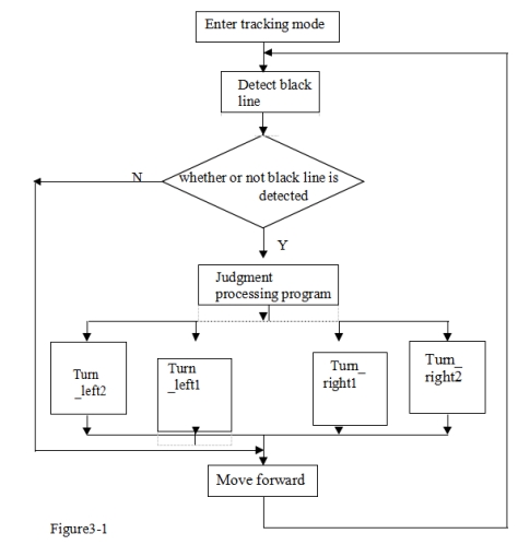
7.Flow chart of line tracking car
When the car enters the tracking mode, it begins constantly scanning I/O port of the MCU. When the I/O port picks up a signal, it will enter the processing; firstly determine which detector detects the black line.
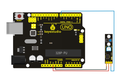
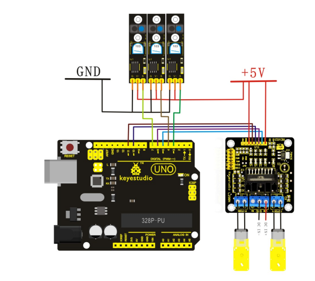
8.Circuit wiring of Arduino tracking car
9.Arduino program for tracking car
Code 3
int MotorRight1=5;
int MotorRight2=6;
int MotorLeft1=10;
int MotorLeft2=11;
const int SensorLeft = 7;	// pin for sensor on the left
const int SensorMiddle= 4 ;// pin for sensor in the middle
const int SensorRight = 3;// pin for sensor on the right
int SL;	// left sensor status
int SM;	// middle sensor status
int SR;	// right sensor status

void setup()
{
    Serial.begin(9600);
    pinMode(MotorRight1, OUTPUT); // pin  8 (PWM)
    pinMode(MotorRight2, OUTPUT); // pin  9 (PWM)
    pinMode(MotorLeft1, OUTPUT); // pin  10 (PWM)
    pinMode(MotorLeft2, OUTPUT); // pin  11 (PWM)
    pinMode(SensorLeft, INPUT); // define left sensor
    pinMode(SensorMiddle, INPUT);// define middle sensor
    pinMode(SensorRight, INPUT); // define right sensor
}


void loop()
{
    SL = digitalRead(SensorLeft);
    SM = digitalRead(SensorMiddle);
    SR = digitalRead(SensorRight);

    if (SM == HIGH)// middle sensor in black area
    {
        if (SL == LOW & SR == HIGH) // black on left, white on right, turn left
        {
            digitalWrite(MotorRight1,LOW);
            digitalWrite(MotorRight2,HIGH);
            analogWrite(MotorLeft1,0);
            analogWrite(MotorLeft2,80);
        }
        else if (SR == LOW & SL == HIGH) // white on left, black on right, turn right
        {
            analogWrite(MotorRight1,0);// turn right
            analogWrite(MotorRight2,80);
            digitalWrite(MotorLeft1,LOW);
            digitalWrite(MotorLeft2,HIGH);
        }
        else // white on both sides, going forward
        {
            digitalWrite(MotorRight1,LOW);
            digitalWrite(MotorRight2,HIGH);
            digitalWrite(MotorLeft1,LOW);
            digitalWrite(MotorLeft2,HIGH);
            analogWrite(MotorLeft1,200);
            analogWrite(MotorLeft2,200);
            analogWrite(MotorRight1,200);
            analogWrite(MotorRight2,200);
        }
    }
    else // middle sensor on white area
    {
        if (SL == LOW & SR == HIGH)// black on left, white on right, turn left
        {
            digitalWrite(MotorRight1,LOW);
            digitalWrite(MotorRight2,HIGH);
            digitalWrite(MotorLeft1,LOW);
            digitalWrite(MotorLeft2,LOW);
        }
        else if (SR == LOW & SL == HIGH) // white on left, black on right, turn right
        {
            digitalWrite(MotorRight1,LOW);
            digitalWrite(MotorRight2,LOW);
            digitalWrite(MotorLeft1,LOW);
            digitalWrite(MotorLeft2,HIGH);
        }
        else // all white, stop
        {
            digitalWrite(MotorRight1,HIGH);
            digitalWrite(MotorRight2,LOW);
            digitalWrite(MotorLeft1,HIGH);
            digitalWrite(MotorLeft2,LOW);
        }
    }
}