Project 5 Buzzer
1.About this circuit
In this project, you will learn how to make tones with a buzzer.
2.What You Need
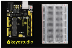
REV4 Baseplate |
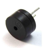
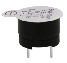
Passive Buzzer x 1 |
Jumper wires x 2 |
USB cable x 1 |
|---|---|---|---|
|
|
|
|


3.Component Introduction:
Buzzers can be categorized as active and passive ones. The difference between the two is that an active buzzer has a built-in oscillating source, so it will generate a sound when electrified.
A passive buzzer does not have such a source, so DC signal cannot drive it beep. Different frequencies produce different sounds. By the buzzer, you can even play a song.
4.Hookup Guide
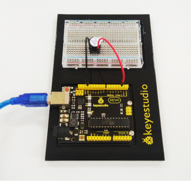
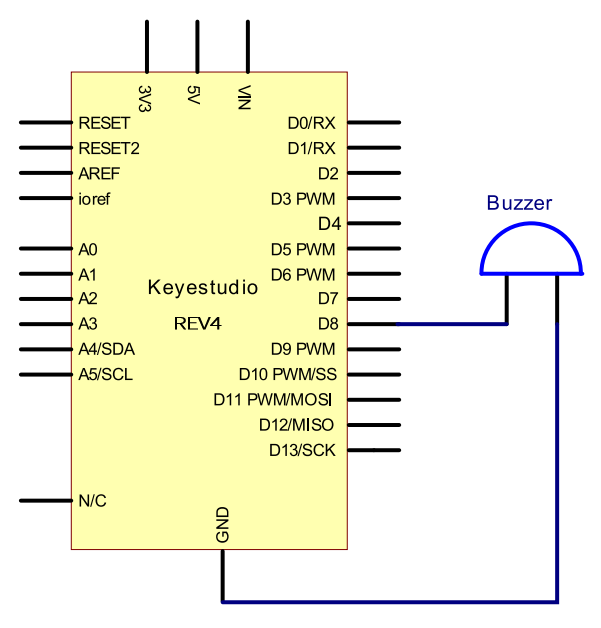
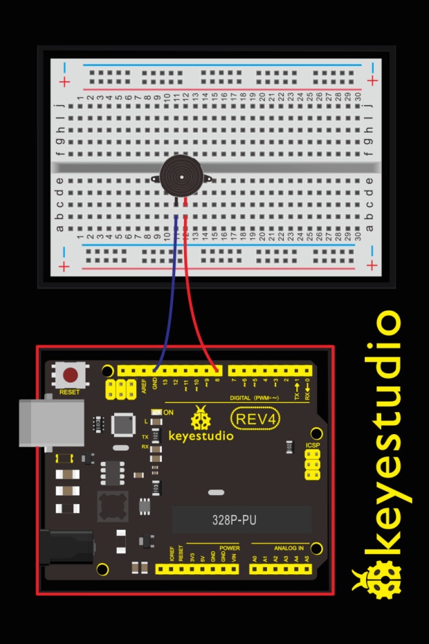
Wiring the buzzer connected to the REV4 board, the red (positive) to the pin8, black wire (negative) to the GND.
5.Upload Code
int buzzer=8;// select digital IO pin for the buzzer

void setup()
{
	pinMode(buzzer,OUTPUT);// set digital IO pin pattern, OUTPUT to be output
}

void loop()
{
    unsigned char i,j;//define variable
    while(1)
    {
        for(i=0;i<80;i++)// output a frequency sound
        {
            digitalWrite(buzzer,HIGH);// sound
            delay(1);//delay1ms
            digitalWrite(buzzer,LOW);//not sound
            delay(1);//ms delay
        }
        for(i=0;i<100;i++)// output a frequency sound
        {
            digitalWrite(buzzer,HIGH);// sound
            digitalWrite(buzzer,LOW);//not sound
            delay(2);//2ms delay
        }
    }
}
6.Test Result
Done uploading the code to the board, the passive buzzer will make a tone.
The following active buzzers are expansion parts
7.active buzzer
The use method is almost the same. Think about it and try to make an audible beep from active buzzer.
Test code is showed below:
int buzzer=2;// initialize digital IO pin that controls the buzzer

void setup()
{
    pinMode(buzzer,OUTPUT);// set pin mode as “output”
}

void loop()
{
	digitalWrite(buzzer, HIGH); // produce sound
}
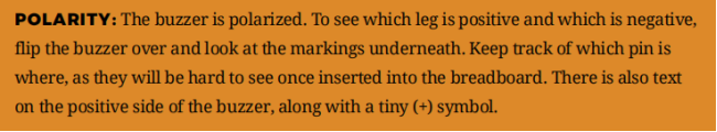
From the test code, we can know the buzzer’s positive lead (long lead) is connected to Digital pin 2 of REV4. The short lead is connected to ground.