Project 9 LED Matrix Display
1.About this circuit
In this circuit, you will learn how to control the LED matrix showing the number.
2.What You Need
REV4 Baseplate |
LED matrix display x 1 |
220Ω Resistor x 8 |
Jumper wires x 16 |
USB cable x 1 |
|---|---|---|---|---|
|
|
|
|
|


3.Component Introduction
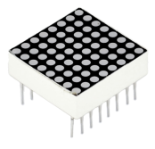
LED Matrix display:
Now, we are going to learn 8*8 dot matrix. It consists of 64 LEDs, located in every crossing of each row and column.
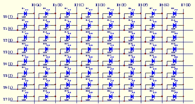
Welding pins on the 8*8 dot matrix:
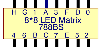
When a row is at level 1, and a column at level 0 simultaneously, LED lights up that is between high and low level. For instance, if you want to light up the first LED, connect pin 7 to high level, and pin A to low level; if you want to light up LEDs in first row, connect pin 7 to high level, and pin A, B, C, D, E, F, G, H to low level; if you want to light up LEDs in first column, connect pin A to high level, and pin 0, 1, 2, 3, 4, 5, 6, 7 to low level shown as below figure.
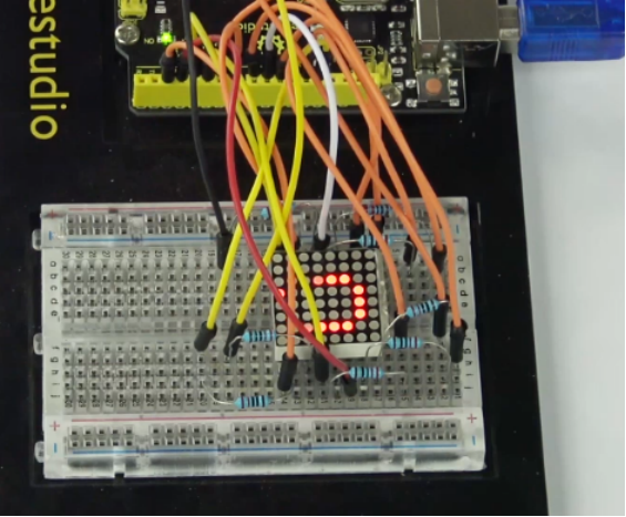
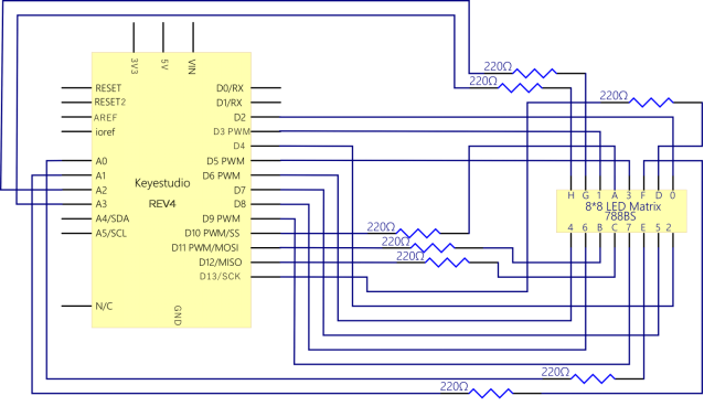
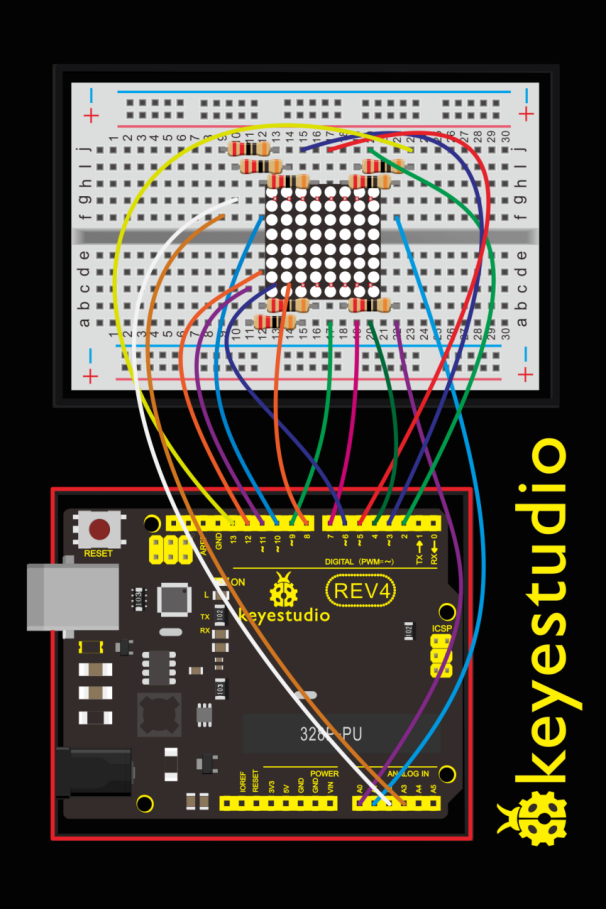
4.Hookup Guide
Check out the circuit diagram and hookup table below to see how everything is connected.
5.Upload Code
//define an array to store “0”
unsigned char Text[]={0x00,0x1c,0x22,0x22,0x22,0x22,0x22,0x1c};
void Draw_point(unsigned char x,unsigned char y)//draw-point function
{
   clear_();
   digitalWrite(x+2, HIGH);
   digitalWrite(y+10, LOW);
   delay(1);
}

void show_num(void)//show function and invoke draw-point function
{
  unsigned char i,j,data;
  for(i=0;i<8;i++)
  {
    data=Text[i];
    for(j=0;j<8;j++)
    {
      if(data & 0x01)Draw_point(j,i);
      data>>=1;
    }
  }
}

void setup()
{
    int i = 0 ;
    for(i=2;i<18;i++)
     {
       pinMode(i, OUTPUT);
      }
      clear_();
}

void loop()
{
    show_num();
}

void clear_(void)//clear screen
{
    for(int i=2;i<10;i++)
    digitalWrite(i, LOW);
    for(int i=0;i<8;i++)
    digitalWrite(i+10, HIGH);
}
6.Result
Hookup well and upload the code to board, the LED matrix is displaying the “0”.