Project 15 Vibration Switch
1.About this circuit
In this circuit you will learn how to test the vibration switch.
2.What You Need
REV4 Baseplate |
Vibration switch x 1 |
10KΩ Resistor x 1 |
Jumper wires x 3 |
USB cable x 1 |
|---|---|---|---|---|
|
|
|
|
|
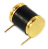


3.Component Introduction

It is a electronic switch that can sense the intensity of vibration and transfer the result to the circuit device, and activate the circuit to start working.
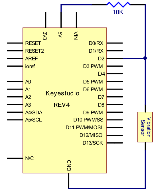
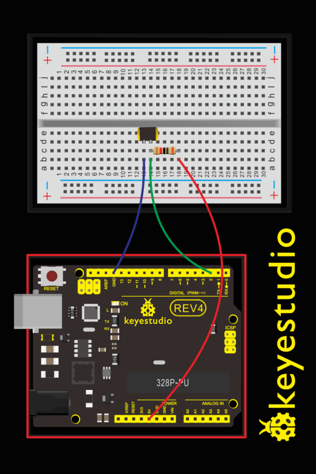
4.Hookup Guide
Check out the circuit diagram and hookup table below to see how everything is connected.
5.Upload Code
#define SensorLED     13
#define SensorINPUT   2
unsigned char state = 0;

void setup()
{
  pinMode(SensorLED, OUTPUT);
  pinMode(SensorINPUT, INPUT);
  attachInterrupt(0, blink, FALLING);//D2 as external interruption 0, when there is falling trigger and call blink function
}

void loop()
{
      if(state!=0)
      {
        digitalWrite(SensorLED,HIGH);
        delay(3000);
        state = 0;
      }
      else
        digitalWrite(SensorLED,LOW);
}

void blink()// digital input of the sensor falling, triggering interruption function
{
  state++;
}
6.What You Will See
Done uploading the code, vibrate the desk where the sensor placed; once the sensor detects vibration, the D13 led on the REV4 board turns on for 3 seconds then off.