Project 23 Remote-Controlled Robot
1.About this circuit
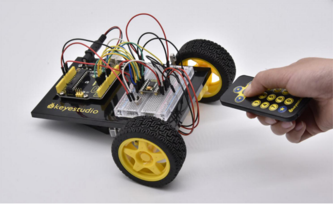
Using an IR Remote is a great way to have wireless control of your project. In this circuit, you’ll control two motors and build your own remote-controlled roving robot!
You can use the remote controller to tell the robot in what direction to move and how far to move.
2.What You Need
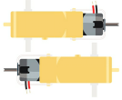
Gear Motor x 2 |
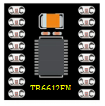
TB6612FNG Motor Driver x 1 |
Slide switch x 1 |
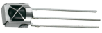
IR receiver x 1 |
Remote controller x 1 |
Jumper wires x 24 |
|---|---|---|---|---|---|
|
|
|
|
|
|


3.Component Introduction
IR Receiver:
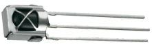
Infrared receiver is a component with functions of reception, amplification, and demodulation.
The internal IC has already been demodulated so that can directly output digital signal.
Infrared receiver has 3 pins. When you use it, connect VOUT to Analog pin, GND to GND, VCC to +5V.
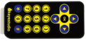
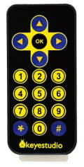
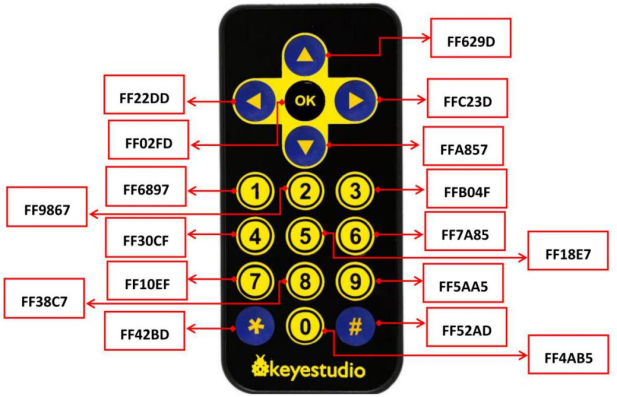
Remote Controller:
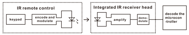
Infrared remote control is composed of infrared transmitting and infrared receiving systems. That is, consist of an infrared remote control, an infrared receiver module and a micro-controller that can decode.
You can refer to the figure below.
Below we have listed out each button value of keyestudio remote control for reference.
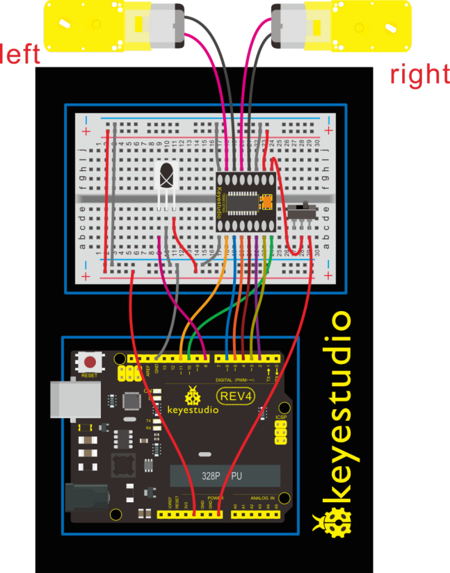
4.Hookup Guide
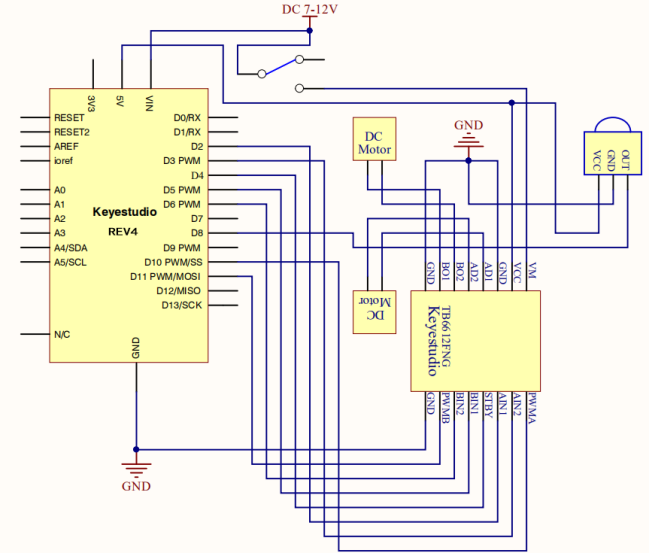
5.Circuit Diagram
6.Upload Code
#include <IRremote.h>
int RECV_PIN = 8;
int LED1 = 13;
unsigned long on1  = 0x00FF6897;
unsigned long off1 = 0x00FF9867;
int AIN1=2;
int AIN2=3;
int STBY=4;
int BIN1=5;
int BIN2=11;
int PWMA=10;// enable pin 1
int PWMB=6;// enable pin 2
unsigned long advance1 = 0x00FF629D;
unsigned long back1 = 0x00FFA857;
unsigned long stop1 = 0x00FF02FD;
unsigned long left1 = 0x00FF22DD;
unsigned long right1 = 0x00FFC23D;
IRrecv irrecv(RECV_PIN);
decode_results results;

void setup()
{
  int i;
  for (i=2;i<=6;i++) // Ardunio motor driver module
  pinMode(i,OUTPUT); // set digital pins 2,3,4,5,6 as output
  pinMode(10,OUTPUT);// set digital pins 10, 11 as output
  pinMode(11,OUTPUT);
  pinMode(LED1, OUTPUT);
  irrecv.enableIRIn(); // Start the receiver
}

void loop()
{
  if (irrecv.decode(&results))
  {
    if (results.value == advance1 )
       front();
    if (results.value == back1 )
       back();
    if (results.value == stop1)
       Stop();
    if (results.value == left1 )
       left();
    if (results.value == right1 )
       right();
    if (results.value == on1 )
       digitalWrite(LED1, HIGH);
    if (results.value == off1 )
       digitalWrite(LED1, LOW);
    irrecv.resume(); // Receive the next value
  }
}

void front()
{
    digitalWrite(STBY,HIGH);
    digitalWrite(AIN1,HIGH);
    digitalWrite(AIN2,LOW);
    analogWrite(PWMA,200);
    digitalWrite(BIN1,HIGH);
    digitalWrite(BIN2,LOW);
    analogWrite(PWMB,200);
}

void back()
{
    digitalWrite(STBY,HIGH);
    digitalWrite(AIN1,LOW);
    digitalWrite(AIN2,HIGH);
    analogWrite(PWMA,200);
    digitalWrite(BIN1,LOW);
    digitalWrite(BIN2,HIGH);
    analogWrite(PWMB,200);
}

void Stop()
{
  digitalWrite(STBY,LOW);
}

void left()
{
    digitalWrite(STBY,HIGH);
    digitalWrite(AIN1,HIGH);
    digitalWrite(AIN2,LOW);
    analogWrite(PWMA,200);
    digitalWrite(BIN1,LOW);
    digitalWrite(BIN2,HIGH);
    analogWrite(PWMB,200);
}

void right()
{
    digitalWrite(STBY,HIGH);
    digitalWrite(AIN1,LOW);
    digitalWrite(AIN2,HIGH);
    analogWrite(PWMA,200);
    digitalWrite(BIN1,HIGH);
    digitalWrite(BIN2,LOW);
    analogWrite(PWMB,200);
}
7.Result
Start by flipping the switch to the ON position. Use remote control to make the robot move or turn.