4.2 Project : Light Control System
In this project, we will construct a light control system by a photoresistor and an LED. It is an intelligent system to adjust light, which saves energy and enhance efficiency as well.

This system is compatible with multiple conditions. Thanks to its photoresistor, it is able to detect the light intensity in day or at night, realizing a more intelligent and energy-saving system.
When the photoresistor detects that ambient brightness is lower than the set value, LED lights up. On the contrary, if the ambient light intensity is higher than the set value, photorisistor will send a different signal to turn off the LED.
4.2.1 Flow Diagram

4.2.2 Photoresistor
Description:
A photoresistor, also called photosensor, converts light signal into electric signal (voltage, current, and resistor).
Working principle:
We place a photoresistor in a circuit in series connection and add suitable voltage to both poles. When there is no light, the resistance is infinite and the circuit almost opens. However, when there is light, the resistance decreases while the current increases, and it is equivalent to a short circuit when the light intensity is sufficient.
Now we will read the value of photoresistor by programming on ESP32 development board.
Schematic Diagram:
When light hits the photoresistor, the stronger the light is, the smaller the resistance will be, so the greater the VCC voltage will pass through the resistor.

Parameters:
Voltage: 3~5V
Current: 0.2mA
Power: 1mW
Spectrum Peak Value: 540nm
Bright Resistance (10lux): 5~10KR
Dark Resistance: 0.5MR
Wiring Diagram:
Connect the photoresistor to io34.
Attention: Connect yellow to S(Signal), red to V(Power), and black to GND. Do not reverse them!

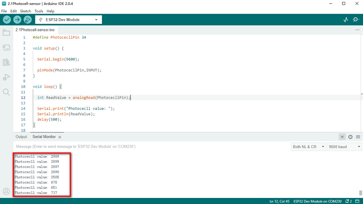
Test Code:
Initialize the serial port.

Define a global variable “item” as the photoresistor value.

Set “item” to the read value and print it on serial monitor.

Complete code:

Test Result:
Open the serial monitor.
The brighter the light detected by the photoresistor is, the greater the value will be.

4.2.3 Light Control System
Wiring Diagram:
Connect the photoresistor to io34 and LED to io27.
Attention: Connect yellow to S(Signal), red to V(Power), and black to GND. Do not reverse them!

Test Code:
Code Flow:

Determine:
The value of the photoresistor >= 800, LED turns off.
The value of the photoresistor =< 800, LED turns on.

Complete code:

Test Result:
When the value of the photoresistor is greater than 800 (in daytime), LED goes off. However, if the value is less than 800, LED will automatically light on.

**Various conditions can adopt this type of system. Thanks to its photoresistor, it is able to detect the light intensity in day or at night, which saves energy and intellectualize the whole system. **
4.2.2 FAQ
Q: The value of the photoresistor cannot be 0.
A: In actual life, little light exists although you turn off all lights in your room, so the value of photoresistor only approaches to 0 rather than equals to 0.
Q: After uploading code, LED doesn’t light up even though the room is dark without lights.
A: Increase the determined value of photoresistor. In our example, we set to 800. So you may adjust it to 1000 or a greater value.