4.7 Project: Temperature Control System
In this project, we will demonstrate how to use temperature and humidity sensor, fan and LCD1602 display to constitute an intelligent temperature and humidity control system.
The system measures ambient temperature and humidity and controls fan to cool down as needed. When the temperature exceeds the set threshold, the fan automatically turns on to reduce the ambient temperature below the set value. Meanwhile, the current temperature and humidity values will be displayed on LCD1602.
Therefore, it realizes automatic adjustment of ambient temperature and humidity, which is perfect for projects that require these functions.

4.7.1 Flow Diagram

4.7.2 Temperature and Humidity Sensor
Description:
DHT11 temperature and humidity sensor outputs digital signals. It applies principles of analog signal acquisition and conversion as well as temperature and humidity sensing technology, so that it features long-term stability and high reliability. Besides, the sensor integrates a high-precision resistive humidity sensor and a resistive thermosensitive temperature sensor, and is connected with an 8-bit high-performance MCU.

DHT11 Communication Means:
DHT11 communicates through monobus(a single bus) which exchanges and controls data.
Monobus transmits Data Bit:
Data format of monobus: transmit 40bit data every time, and high-bit first.
8bit humidity integer value + 8bit humidity decimal value + 8bit temperature integer value + 8bit temperature decimal value + bit parity.
NOTE: Humidity decimal value equals 0.
Paraty Bit:
8bit humidity integer value + 8bit humidity decimal value + 8bit temperature integer value + 8bit temperature decimal value.
8bit parity equals the end 8 bits of the result.
Timing Diagram:

**NOTE: **
The host always reads the temperature and humidity values of last measurement from DHT11. Therefore, If the interval between two measurements is long, please consecutively detect twice and adopt the second result.
For more details, please visit ASAIR official website: http://www.aosong.com/products-21.html
Wiring Diagram:
Connect the temperature and humidity sensor to io17.
Attention: Connect yellow to S(Signal), red to V(Power), and black to GND. Do not reverse them!

Test Code:
Initialize the serial port and the sensor.

The serial monitor prints and refreshes humidity and temperature values per second.

Complete code:

Test Result:

Open the serial monitor, and you will see the current temperature and humidity value.

4.7.3 LCD 1602 Module
Description:
LCD 1602 possesses a standard 14-pin (without back light) or 16-pin (with back light) interface, saving the pins of MCU. Its display drives IC to realize I2C control.

I2C Serial Communication:
I2C communication, known fully as Inter-Integrated Circuit (IIC) or Two-Wire Interface (TWI), is a commonly-used dual-bus (a host and a slave) communication protocol, which is developed by Phillips Semiconductor (purchased by US NXP Semiconductors).
The biggest advantage is that only two wires complete the transmission of data, which largely simplifies circuits. In total, I2C bus can connect 127 nodes in parallel, so it supports multiple hosts and slaves.
Generally, external power supply is needless for slaves, as I2C bus will transmit the power to them:

I2C bus transmits data via 8-bit data transmission. Usually, one-byte-data is composed of nine clock signals, eight of which transmit data and the last one marks the end of transmission.
Moreover, I2C bus supports multi-byte data transmission by repeating the above process continuously.
I2C Protocol basically consists of:
Starting signal: Before transmission, sender transmits a starting signal to inform receiver of starting point.
Address: It notifies receiver to whom the data is being sent.
Data: It is transmitted one byte each time and bit by bit.
Ending Signal: When finishing transmission, sender ends data with an ending signal to inform receiver that process is over.
Timing Diagram of Serial Protocol:
For more details, please visit the official website: https://www.nxp.com/


We provide you with a library file Wire.h for I2C protocol, in which functions can be directly called to communicate with I2C/TWI devices.
For details of library, please refer to:
https://www.arduino.cc/reference/en/language/functions/communication/wire/
Wiring Diagram:
Connect the LCD to I2C BUS as shown below.
Attention: Connect yellow to S(Signal), red to V(Power), and black to GND. Do not reverse them!

Test Code:
Initialize I2C address of LCD and turn on its back light.

Set the LCD cursor position in X and Y axis (X-axis displays a maximum of 16 characters, and Y-axis displays a maximum of 2 columns).

Input the print content (No more than 16 characters, otherwise it will not be complete).

Complete code:

Test Result:
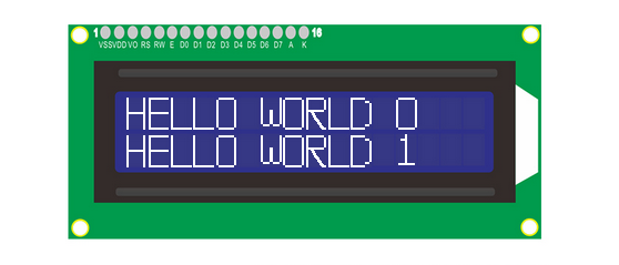
LCD1602 opens its back light and displays ” HELLO WORLD 0 “ and ” HELLO WORLD 1 “.
4.7.4 Fan Module
Description:
130 Motor is able to adjust speed via PWM. In the process, two pins are needed to be connected for controlling.
The module is suitable for multiple applications, such as computer heat dissipation and industrial production. What’s more it is compact and easy to install, which is very practical.

Schematic Diagram:

Wiring Diagram:
Connect the motor to io18 and io19.
Attention: Connect yellow to S(Signal), red to V(Power), and black to GND. Do not reverse them!

Test Code:
Set fan pin INA

Set the power level state of INA, which determines the rotation direction of fan.

Set fan pin INB.

Set the analog output at INB, which decides the rotation speed.
When INA is at high, the lower the analog output at INB is, the faster the fan will rotate.
When INA is at low, the greater the analog output at INB is, the faster the fan will rotate.

Test Result:
130 motor alternatively rotates left and right every 2 seconds.

**NOTE: **
Intermittent stops exist during changing directions of rotation. They prevent an excessive current at the moment of reversal. Otherwise, a forced reset may occur due to insufficient power supply on the development board.
4.7.5 Temperature Control System
Description:
Herein, we read the value of the DHT11 temperature and humidity sensor through monobus communication, and the values will be displayed on the LCD. If values exceed the set threshold, the fan will turn on for dehumidification and cooling to protect the animals and plants in the farm. Remarkably, this system is easy to install with multiple functions, such as speed controlling via PWM and data transmission by monobus.
Overall, it is a practical system that helps farmers monitor and control the real-time status to improve production efficiency.
Wiring Diagram:
Connect the temperature and humidity sensor to io17.
Connect motor(fan) modue to io18 and io19
Connect LCD1602 to BUS I2C.
Attention: Connect yellow to S(Signal), red to V(Power), and black to GND. Do not reverse them!

Test Code:
Code Flow:

Code:
Initialize LCD to set an address, and clear the display. Turn on its backlight and set cursor position:

Initialize the DHT11 sensor and choose a corresponding pin. Define two variables as temperature and humidity values.

In the loop, respectively assign the detected values to the two variables.

Display the values on LCD.

Determine the temperature and humidity value. if temperature is higher than 29° or humidity exceeds 80, fan will rotate.

Complete code:

Test Result:
When the temperature reaches 29°C, the fan will turn on to dissipate heat. When it is lower than 29°C, the fan will turn off (the fan just simulates heat dissipation, so the effect is not good), which saves energy for the farm.
4.7.6 FAQ
#Q: Is temperature and humidty sensor waterproof?
A: No. It detects the ambient temperature and humidity (in the air), so please do not put it in water.
#Q: ESP32 board is reset when fan rotates.
A: When fan rotates, more current is required than other sensors, hence voltage and current may fluctuate in the circuit. Especially at the moment of fan reversal, fluctuations may be too heavy, resulting in a reset due to extremely low voltage and current in ESP32 development board.