5.1 Sistema de Iluminación
5.1.1 Encender un LED
Abre el código 5.1.1Blink con Arduino IDE.
#define LED_BUILTIN 27  //LED pins

void setup() {
  // initialize digital pin LED_BUILTIN as an output.
  pinMode(LED_BUILTIN, OUTPUT);
}

// the loop function runs over and over again forever
void loop() {
  digitalWrite(LED_BUILTIN, HIGH);  // turn the LED on (HIGH is the voltage level)
  delay(1000);                      // wait for a second
  digitalWrite(LED_BUILTIN, LOW);   // turn the LED off by making the voltage LOW
  delay(1000);                      // wait for a second
}
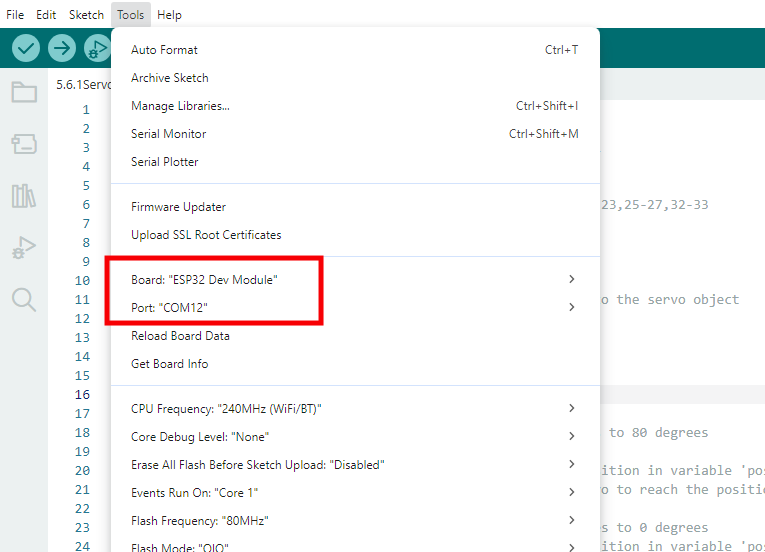
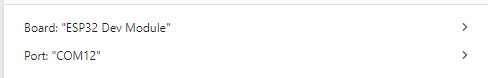
Elige la placa ESP32 Dev Module y el puerto COM, y sube el código.
Resultado de la prueba:
El LED parpadea por segundo, porque io27 en la placa ESP32 emite nivel alto y bajo alternativamente cada segundo.
Nivel de potencia |
Resultado |
|---|---|
HIGH |
LED ENCENDIDO |
LOW |
LED APAGADO |
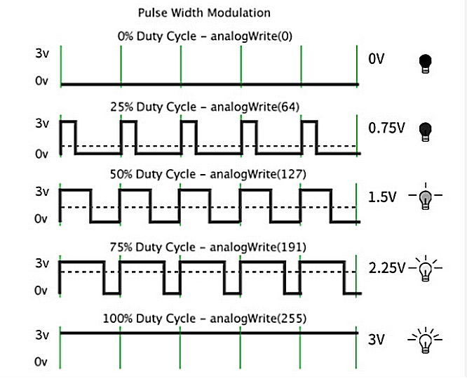
5.1.2 Controlar el LED con PWM
Abre el código 5.1.2PWM con Arduino IDE.
#define led 27    //Define LED pin

void setup(){
  pinMode(led, OUTPUT);  //Set pin to output mode
}

void loop(){
  for(int i=0; i<255; i++)  //for loop statement. Constantly increase variable i till 255, exit the loop
  {
    analogWrite(led, i);  //PWM output, used to control the brightness of LED
    delay(3);
  }
  for(int i=255; i>0; i--)  //for loop statement. Constantly decrease variable i till 0, exit the loop
  {
    analogWrite(led, i);
    delay(3);
  }
}
Elige la placa ESP32 Dev Module y el puerto COM, y sube el código.
Resultado de la prueba:
A una frecuencia de señal adecuada, PWM cambia el voltaje de salida efectivo al cambiar el ciclo de trabajo en un período. En términos sencillos, dentro de un tiempo especificado, cuanto mayor sea el nivel alto que emita el puerto IO, mayor será el valor PWM y más brillante será el LED.
El módulo LED se encenderá lentamente de oscuro a brillante, y luego de brillante a oscuro.
5.1.3 Leer el valor digital del botón
Abre el código 5.1.3Button con Arduino IDE.
#define ButtonPin 5 //Define the button pin to 5

void setup() {
  //initialize serial port and set baud rate to 9600
  Serial.begin(9600);
  //Set pin to input mode
  pinMode(ButtonPin,INPUT);
}

void loop() {
  //Define a value as the read button value
  int ReadValue = digitalRead(ButtonPin);
  //Serial port prints the defined value
  Serial.print("The current status of the button is : ");
  Serial.println(ReadValue);
  delay(500);
}
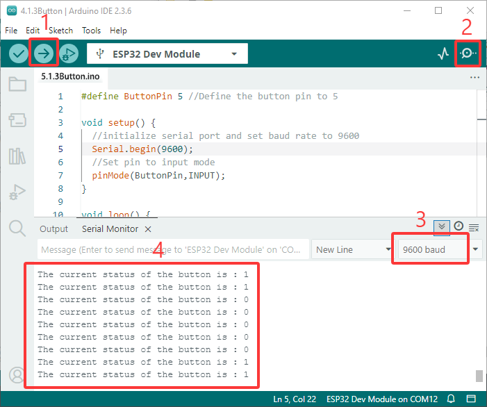
Elige la placa ESP32 Dev Module y el puerto COM, y sube el código.
Resultado de la prueba:
Abre el monitor serie y establece la velocidad de transmisión en 9600.
Cuando el botón está suelto, el valor es 1; si presionas el botón, se convierte en 0.
El principio del módulo de botón es un circuito controlado por este botón.
Cuando se presiona el botón, el circuito se cierra para que la corriente pase a través del botón a GND, lo que hace que el pin de entrada digital detecte un nivel bajo.
Cuando se suelta el botón, el circuito se corta y el nivel del pin aumenta debido a una resistencia pull-up, lo que hace que el pin digital detecte un nivel alto.
5.1.4 Botón de auto-bloqueo
Abre el código 5.1.4 Self-Locking_Button con Arduino IDE.
#define ButtonPin 5 //Define the button pin
int value = 0;      //Define a value to determine the status of button

void setup() {
  //Initialize the serial port and set baud rate to 9600
  Serial.begin(9600);
  //Set the pin to inpu tmode
  pinMode(ButtonPin,INPUT);
}

void loop() {
  //Define a value as the read button value
  int ReadValue = digitalRead(ButtonPin);
  //Detect whether the button is pressed
  if (ReadValue == 0) {
    //Eliminate the button shake
    delay(10);
    if (ReadValue == 0) {
      value = !value;
      Serial.print("The current status of the button is : ");
      Serial.println(value);
    }
    //Detect again whether the button is still pressed
    //Pressed: execute the loop; Released: exit the loop to next step
    while (digitalRead(ButtonPin) == 0);
  }
}
Elige la placa ESP32 Dev Module y el puerto COM, y sube el código.
Resultado de la prueba:
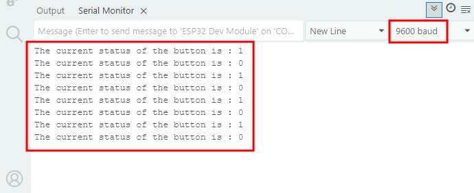
Abre el monitor serie y establece la velocidad de transmisión en 9600.
Cuando presionas el botón una vez, se mostrará 1. Si presionas el botón por segunda vez, el valor se convierte en 0. Ahora, un botón común cuenta con la función de uno de auto-bloqueo.
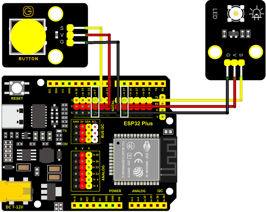
5.1.5 Usar el botón para controlar el módulo LED
Abre el código 5.1.5 Lighting-System con Arduino IDE.
#define ButtonPin 5   //Define a button pin
#define LED       27  //Define LED pin
int value = 0;        //Define a value to detect button status

void setup() {
  //initialize serial port and set baud rate to 9600
  Serial.begin(9600);
  //Set pin to input mode
  pinMode(ButtonPin,INPUT);
  //Set pin to output mode
  pinMode(LED,OUTPUT);
}

void loop() {
  //Define a value as the read button value
  int ReadValue = digitalRead(ButtonPin);
  //Detect whether the button is pressed
  if (ReadValue == 0) {
    //Eliminate the button shake
    delay(10);
    if (ReadValue == 0) {
      value = !value;
      //Detect the button status, press once to light up LED, press again to turn off LED, in a loop
      if(value) {
        digitalWrite(LED,HIGH);
      }else{
        digitalWrite(LED,LOW);
      }
    }
    //Detect the button status again
    //Pressed: execute the loop; Released: exit the loop to next step
    while (digitalRead(ButtonPin) == 0);
  }
}
Elige la placa ESP32 Dev Module y el puerto COM, y sube el código.
Resultado de la prueba:
Cuando presionas el botón una vez, el LED se enciende; si presionas de nuevo, el LED se apaga. Esta operación es un bucle, lo cual es consistente con el principio de iluminación en la realidad.