Project 12 IR Remote Control Robot
1. Description
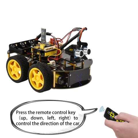
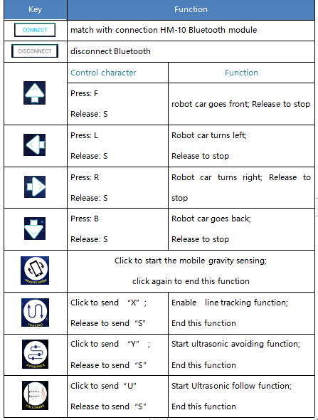
We combine the hardware knowledge – sensors, motor drive, and IR receiver, to build an infrared remote control robot car! In the IR receiver section, we’ve listed out each key value of remote control. In this circuit design, we can set the key value in the code to navigate the robot car movement. The corresponding state pattern is displayed on the 8*16 LED matrix.
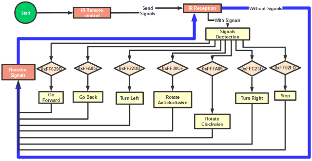
The specific logic of infrared remote control robot car is shown below:
Based on the circuit design, we can start building our own remote control robot.
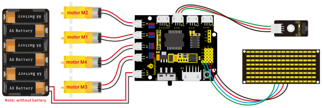
2. Hook-up Diagram
3. Test Code
/*
keyestudio 4wd BT Car V2.0
lesson 12
remote control robot
http://www.keyestudio.com
*/
//Array, used to store the data of pattern, can be calculated by yourself or obtained from the modulus tool
unsigned char start01[] = {0x01,0x02,0x04,0x08,0x10,0x20,0x40,0x80,0x80,0x40,0x20,0x10,0x08,0x04,0x02,0x01};
unsigned char front[] = {0x00,0x00,0x00,0x00,0x00,0x24,0x12,0x09,0x12,0x24,0x00,0x00,0x00,0x00,0x00,0x00};
unsigned char back[] = {0x00,0x00,0x00,0x00,0x00,0x24,0x48,0x90,0x48,0x24,0x00,0x00,0x00,0x00,0x00,0x00};
unsigned char left[] = {0x00,0x00,0x00,0x00,0x00,0x00,0x44,0x28,0x10,0x44,0x28,0x10,0x44,0x28,0x10,0x00};
unsigned char right[] = {0x00,0x10,0x28,0x44,0x10,0x28,0x44,0x10,0x28,0x44,0x00,0x00,0x00,0x00,0x00,0x00};
unsigned char STOP01[] = {0x2E,0x2A,0x3A,0x00,0x02,0x3E,0x02,0x00,0x3E,0x22,0x3E,0x00,0x3E,0x0A,0x0E,0x00};
unsigned char clear[] = {0x00,0x00,0x00,0x00,0x00,0x00,0x00,0x00,0x00,0x00,0x00,0x00,0x00,0x00,0x00,0x00};
#define SCL_Pin  A5  //Set clock pin to A5
#define SDA_Pin  A4  //Set data pin to A4
#define ML_Ctrl 4     //define direction control pin of B motor
#define ML_PWM 5   //define PWM control pin of B motor
#define MR_Ctrl 2    //define direction control pin of A motor
#define MR_PWM 6   //define PWM control pin of A motor
#include <IRremote.h>//function library of IR remote control
int RECV_PIN =3;// set the pin of IR receiver to 3
IRrecv irrecv(RECV_PIN);
long irr_val;
decode_results results;

void setup()
{
    pinMode(ML_Ctrl, OUTPUT);//define direction control pin of B motor to OUTPUT
    pinMode(ML_PWM, OUTPUT);//define PWM control pin of B motor to OUTPUT
    pinMode(MR_Ctrl, OUTPUT);//define direction control pin of A motor to OUTPUT
    pinMode(MR_PWM, OUTPUT);//define PWM control pin of A motor to OUTPUT
    Serial.begin(9600);//Start serial printing, baud rate is 9600
    // In case the interrupt driver crashes on setup, give a clue
    // to the user what's going on.
    irrecv.enableIRIn(); // Start the receiver
    Serial.println("Enabled IRin");
    //Set pin to output
    pinMode(SCL_Pin,OUTPUT);
    pinMode(SDA_Pin,OUTPUT);
    //Clear the matrix display
    matrix_display(clear);
    matrix_display(start01);
}

void loop()
{
    if (irrecv.decode(&results))
    {
        irr_val = results.value;
        Serial.println(irr_val, HEX);//serial reads the IR remote signals
        switch(irr_val)
        {
            case 0xFF629D : car_front(); matrix_display(front); break;
            case 0xFFA857 : car_back(); matrix_display(back); break;
            case 0xFF22DD : car_left(); matrix_display(left); break;
            case 0xFFC23D : car_right(); matrix_display(right); break;
            case 0xFF02FD : car_Stop(); matrix_display(STOP01); break;
        }
        irrecv.resume(); // Receive the next value
    }
}

void car_front()//car goes forward
{
    digitalWrite(ML_Ctrl,HIGH);//set direction control pin of B motor to HIGH level
    analogWrite(ML_PWM,200);//Set PWM control speed of B motor to 20
    digitalWrite(MR_Ctrl,HIGH);//set direction control pin of A motor to HIGH level
    analogWrite(MR_PWM,200);//Set PWM control speed of A motor to 20
}

void car_back()//car goes back
{
    digitalWrite(ML_Ctrl,LOW);//set direction control pin of B motor to LOW
    analogWrite(ML_PWM,200);//set PWM control speed of B motor to 200
    digitalWrite(MR_Ctrl,LOW);//set direction control pin of A motor to LOW
    analogWrite(MR_PWM,200);//set PWM control speed of A motor to 200
}

void car_left()//car turns left
{
    digitalWrite(ML_Ctrl,LOW);//set direction control pin of B motor to LOW
    analogWrite(ML_PWM,200);//set PWM control speed of B motor to 200
    digitalWrite(MR_Ctrl,HIGH);//set direction control pin of A motor to HIGH level
    analogWrite(MR_PWM,200);//set PWM control speed of A motor to 200
}

void car_right()//car turns right
{
    digitalWrite(ML_Ctrl,HIGH);//set direction control pin of B motor to HIGH level
    analogWrite(ML_PWM,200);//set PWM control speed of B motor to 200
    digitalWrite(MR_Ctrl,LOW);//set direction control pin of A motor to LOW
    analogWrite(MR_PWM,200);//set PWM control speed of A motor to 200
}

void car_Stop()//car stops
{
    analogWrite(ML_PWM,0);//set PWM control speed of B motor to 0
    analogWrite(MR_PWM,0);//set PWM control speed of A motor to 0
}

//this function is used for dot matrix display
void matrix_display(unsigned char matrix_value[])
{
    IIC_start();  //the function to call the data transmission
    IIC_send(0xc0);  //Select address
    for(int i = 0;i < 16;i++) //Pattern data has 16 bytes
    {
        IIC_send(matrix_value[i]); //data to convey patterns
    }
    IIC_end();   //end the transmission of patterns data
    IIC_start();
    IIC_send(0x8A);  //display control, set pulse width to 4/16
    IIC_end();
}

//  the condition that data transmission starts
void IIC_start()
{
    digitalWrite(SCL_Pin,HIGH);
    delayMicroseconds(3);
    digitalWrite(SDA_Pin,HIGH);
    delayMicroseconds(3);
    digitalWrite(SDA_Pin,LOW);
    delayMicroseconds(3);
}

// transmit data
void IIC_send(unsigned char send_data)
{
    for(char i = 0;i < 8;i++)  //Every character has 8 bits
    {
        digitalWrite(SCL_Pin,LOW);  //pull down the SCL_Pin to change the signal of SDA
        delayMicroseconds(3);
        if(send_data & 0x01)  //1 or 0 of byte is used to set high and low level of SDA_Pin
        {
        	digitalWrite(SDA_Pin,HIGH);
        }
        else
        {
        	digitalWrite(SDA_Pin,LOW);
        }
        delayMicroseconds(3);
        digitalWrite(SCL_Pin,HIGH); //Pull up SCL_Pin to stop data transmission
        delayMicroseconds(3);
        send_data = send_data >> 1;  //Detect bit by bit, so move the data right by one bit
    }
}

//the sign that data transmission ends
void IIC_end()
{
    digitalWrite(SCL_Pin,LOW);
    delayMicroseconds(3);
    digitalWrite(SDA_Pin,LOW);
    delayMicroseconds(3);
    digitalWrite(SCL_Pin,HIGH);
    delayMicroseconds(3);
    digitalWrite(SDA_Pin,HIGH);
    delayMicroseconds(3);
}
4. Test Result
Upload the code successfully on the keyestudio V4.0 board and then wire according to the connection diagram. After DIP switch is dialed to the right end, we can use the infrared remote control to control the movement of the smart car . At the same time, the 8X16 LED light board displays the corresponding state pattern.