Project 10 Ultrasonic Avoiding Robot
 vv
vv
1. Description
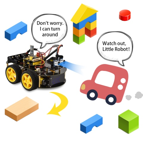
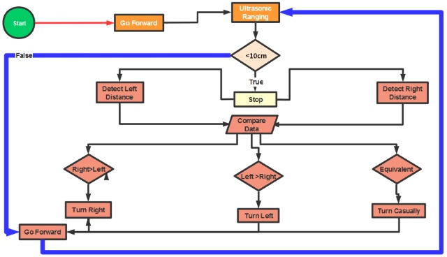
We combine the hardware knowledge – LED matrix, motor drive, ultrasonic and servo, to build an ultrasonic avoiding robot! In the circuit process, we can make use of ultrasonic sensor to detect the distance between robot and front obstacles. Control the motor rotating by measured data, thus control the robot motion and show the running state by dot matrix. The ultrasonic avoiding capability is almost the same as the ultrasonic following function. We only need to change the source code. The specific logic of ultrasonic avoiding smart car is as shown below:
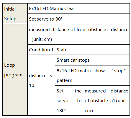
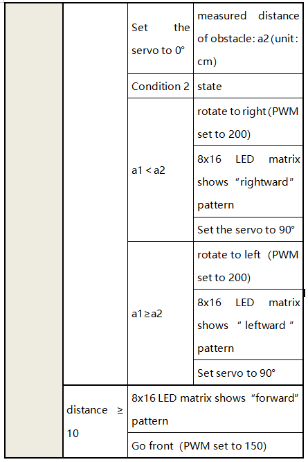
Flow Chart
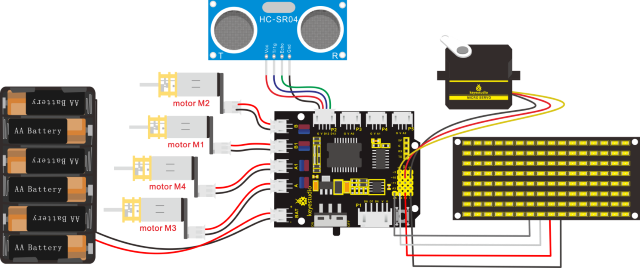
2. Connection Diagram
3. Test Code
/*
keyestudio 4wd BT Car V2.0
lesson 10
ultrasonic avoiding robot
http://www.keyestudio.com
*/
//Array, used to store the data of pattern, can be calculated by yourself or obtained from the modulus tool
unsigned char front[] = {0x00,0x00,0x00,0x00,0x00,0x24,0x12,0x09,0x12,0x24,0x00,0x00,0x00,0x00,0x00,0x00};
unsigned char left[] = {0x00,0x00,0x00,0x00,0x00,0x00,0x44,0x28,0x10,0x44,0x28,0x10,0x44,0x28,0x10,0x00};
unsigned char right[] = {0x00,0x10,0x28,0x44,0x10,0x28,0x44,0x10,0x28,0x44,0x00,0x00,0x00,0x00,0x00,0x00};
unsigned char STOP01[] = {0x2E,0x2A,0x3A,0x00,0x02,0x3E,0x02,0x00,0x3E,0x22,0x3E,0x00,0x3E,0x0A,0x0E,0x00};
unsigned char clear[] = {0x00,0x00,0x00,0x00,0x00,0x00,0x00,0x00,0x00,0x00,0x00,0x00,0x00,0x00,0x00,0x00};
#define SCL_Pin  A5  //Set clock pin to A5
#define SDA_Pin  A4  //Set data pin to A4
#define ML_Ctrl 4     //define direction control pin of B motor
#define ML_PWM 5   //define PWM control pin of B motor
#define MR_Ctrl 2    //define direction control pin of A motor
#define MR_PWM 6   //define PWM control pin of A motor
#include "SR04.h"//define the library of ultrasonic sensor
#define TRIG_PIN 12// set the signal input of ultrasonic sensor to D12
#define ECHO_PIN 13//set the signal output of ultrasonic sensor to D13
SR04 sr04 = SR04(ECHO_PIN,TRIG_PIN);
long distance,a1,a2;//define three distance
const int servopin = 10;//set the pin of servo to D10

void setup()
{
    Serial.begin(9600);//open serial monitor and set baud rate to 9600
    pinMode(ML_Ctrl, OUTPUT);//set direction control pin of B motor to OUTPUT
    pinMode(ML_PWM, OUTPUT);//set PWM control pin of B motor to OUTPUT
    pinMode(MR_Ctrl, OUTPUT);//set direction control pin of A motor to OUTPUT

    pinMode(MR_PWM, OUTPUT);//set PWM control pin of A motor to OUTPUT
    servopulse(servopin,90);// the angle of servo is 90 degree
    delay(300);
    pinMode(SCL_Pin,OUTPUT);//  set clock pin to OUTPUT
    pinMode(SDA_Pin,OUTPUT);//set data pin to OUTPUT
    matrix_display(clear);// Clear the matrix display
}

void loop()
{
    avoid();//run the main program
}

void avoid()
{
    distance=sr04.Distance(); //obtain the value detected by ultrasonic sensor
    if((distance < 20)&&(distance > 0))//if the distance is greater than 0 and less than 20
    {
        car_Stop();//stop
        matrix_display(STOP01);   //show stop pattern
        delay(100);
        servopulse(servopin,180);//servo rotates to 180°
        delay(500);
        a1=sr04.Distance();//measure the distance
        delay(100);
        servopulse(servopin,0);//rotate to 0 degree
        delay(500);
        a2=sr04.Distance();//measure the distance
        delay(100);
        if(a1 > a2)//if distance a1 is greater than a2
        {
            car_left();//turn left
            matrix_display(left);   //display left-turning pattern
            servopulse(servopin,90);//servo rotates to 90 degree
            delay(300);
            matrix_display(front);   //show forward pattern
        }
        else//if the right distance is greater than the left
        {
            car_right();// turn right
            matrix_display(right);   // display right-turning pattern
            servopulse(servopin,90);// servo rotates to 90 degree
            delay(300);
            matrix_display(front);   //show forward pattern
        }
    }
    else//otherwise
    {
        car_front();//go forward
        matrix_display(front);   // show forward pattern
    }
}

void servopulse(int servopin,int myangle)//the running angle of servo
{
    for(int i=0; i<30; i++)
    {
        int pulsewidth = (myangle*11)+500;
        digitalWrite(servopin,HIGH);
        delayMicroseconds(pulsewidth);
        digitalWrite(servopin,LOW);
        delay(20-pulsewidth/1000);
    }
}

void car_front()//car goes forward
{
    digitalWrite(ML_Ctrl,HIGH);//set direction control pin of B motor to HIGH level
    analogWrite(ML_PWM,150);//set PWM control speed of B motor to 150
    digitalWrite(MR_Ctrl,HIGH);//set direction control pin of A motor to HIGH level
    analogWrite(MR_PWM,150);//set PWM control speed of A motor to 150
}

void car_back()//go back
{
    digitalWrite(ML_Ctrl,LOW);//set direction control pin of B motor to LOW
    analogWrite(ML_PWM,200);//set PWM control speed of B motor to 200
    digitalWrite(MR_Ctrl,LOW);//set direction control pin of A motor to LOW
    analogWrite(MR_PWM,200);//set PWM control speed of A motor to 200
}

void car_left()//car turns left
{
    digitalWrite(ML_Ctrl,LOW);//set direction control pin of B motor to LOW
    analogWrite(ML_PWM,200);//set PWM control speed of B motor to 200
    digitalWrite(MR_Ctrl,HIGH);//set direction control pin of A motor to HIGH
    analogWrite(MR_PWM,200);//set PWM control speed of A motor to 200
}

void car_right()//car turn rights
{
    digitalWrite(ML_Ctrl,HIGH);//set direction control pin of B motor to HIGH
    analogWrite(ML_PWM,200);//set PWM control speed of B motor to 200
    digitalWrite(MR_Ctrl,LOW);//set direction control pin of A motor to LOW
    analogWrite(MR_PWM,200);//set PWM control speed of A motor to 200
}

void car_Stop()//car stops
{
    digitalWrite(ML_Ctrl,LOW);
    analogWrite(ML_PWM,150);
    digitalWrite(MR_Ctrl,LOW);
    analogWrite(MR_PWM,150);
    delay(50);
    analogWrite(ML_PWM,0);//set PWM control speed of B motor to 0
    analogWrite(MR_PWM,0);//set PWM control speed of A motor to 0
}

//this function is used for dot matrix display
void matrix_display(unsigned char matrix_value[])
{
    IIC_start();  //the function to call the data transmission
    IIC_send(0xc0);  //Select address
    for(int i = 0;i < 16;i++) //Pattern data has 16 bytes
    {
    	IIC_send(matrix_value[i]); //data to convey patterns
    }
    IIC_end();   //end the transmission of patterns data
    IIC_start();
    IIC_send(0x8A);  //display control, set pulse width to 4/16
    IIC_end();
}

//  the condition that data transmission starts
void IIC_start()
{
    digitalWrite(SCL_Pin,HIGH);
    delayMicroseconds(3);
    digitalWrite(SDA_Pin,HIGH);
    delayMicroseconds(3);
    digitalWrite(SDA_Pin,LOW);
    delayMicroseconds(3);
}

// transmit data
void IIC_send(unsigned char send_data)
{
    for(char i = 0;i < 8;i++)  //Every character has 8 bits
    {
    	digitalWrite(SCL_Pin,LOW);  //pull down the SCL_Pin to change the signal of SDA
    	delayMicroseconds(3);
        if(send_data & 0x01)  //1 or 0 of byte  is used to set high and low level of SDA_Pin
        {
            digitalWrite(SDA_Pin,HIGH);
        }
        else
        {
            digitalWrite(SDA_Pin,LOW);
        }
        delayMicroseconds(3);
        digitalWrite(SCL_Pin,HIGH); //Pull up SCL_Pin to stop data transmission
        delayMicroseconds(3);
        send_data = send_data >> 1;  //Detect bit by bit, so move the data right by one bit
   }
}

//the sign that data transmission ends
void IIC_end()
{
    digitalWrite(SCL_Pin,LOW);
    delayMicroseconds(3);
    digitalWrite(SDA_Pin,LOW);
    delayMicroseconds(3);
    digitalWrite(SCL_Pin,HIGH);
    delayMicroseconds(3);
    digitalWrite(SDA_Pin,HIGH);
    delayMicroseconds(3);
}
4. Test Result
Upload the code on the keyestudio V4.0 board and wire according to connection diagram. After the DIP switch is dialed to the right end, the smart car can automatically avoid obstacles.