Lesson 3.1: Read the Digital Signal of Button Module
(1)Description
In this project, we intend to use the push button module to control the LED.
(2)Parameters:
Working voltage:DC 3.3-5V
Control signal:digital signal
Size:34mm
Weight:3.8g
(3)You need to prepare:
Control Board*1 |
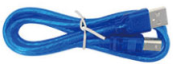
USB Cable*1 |
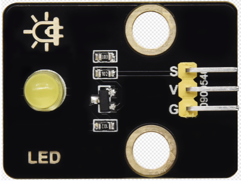
Yellow LED Module*1 |
3pin F-F 26AWG Wire*2 |
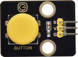
Push Button Module*1 |
|---|---|---|---|---|
|
|
|
|
|


(4)Connection Diagram
Pin Connection Table |
|
|---|---|
Pin of the Button |
Pin of Control Board |
G |
G(GND) |
V |
V(5V) |
S |
D2 |
Pin Connection Table |
|
|---|---|
Pin of the LED |
Pin of Control Board |
G |
G(GND) |
V |
V(5V) |
S |
D3 |

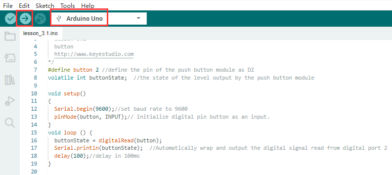

(5)Code Explanation:
Serial.begin(9600)-initialize the serial communication and set the baud rate to 9600
pinMode(pin, INPUT)-use the function pinMode() to tell Arduino whether it is an output pin or an input pin
digitalRead(pin)-read the digital level of pins,be HIGHT OT LOW