Lesson 4.1: Passive Buzzer
(1)Description
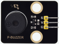
There are prolific interactive works completed by Arduino. The most common one is sound and light display. We always use LED to make experiments. For this lesson, we design circuit to emit sound. The universal sound components are buzzer and horns. Buzzer is easier to use. And buzzer includes about active buzzer and passive buzzer. In this experiment, we adopt passive buzzer.
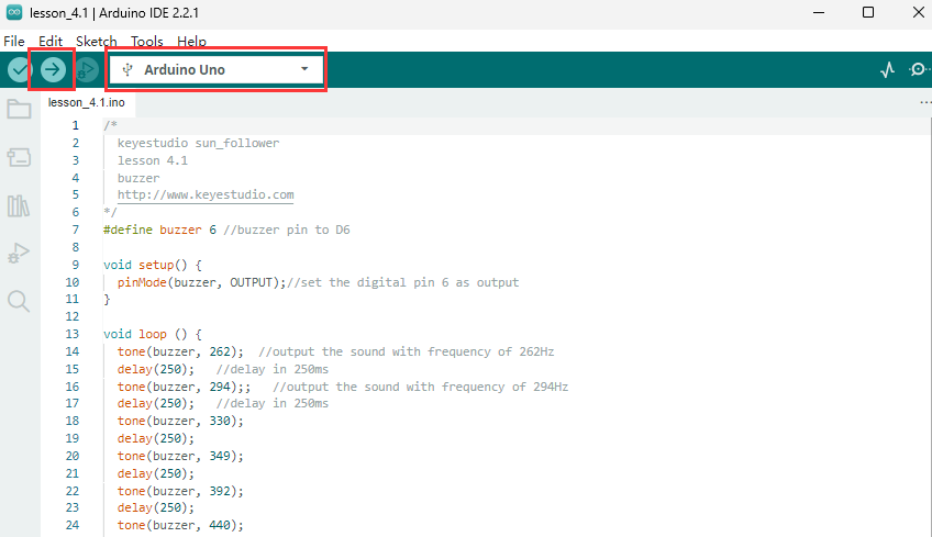
While using passive buzzer, we can control different sound by inputting square waves with distinct frequency. During the experiment, we control code to make buzzer sound, begin with “tick, tick” sound, then make passive buzzer emit “do re mi fa so la si do”, and play specific songs.
(2)Parameters:
Control interface: digital port
Working voltage: DC 3.3-5V
(3)You need to prepare:
Control Board*1 |
USB Cable*1 |
Passive Buzzer*1 |
3pin F-F 26AWG Wire |
|---|---|---|---|
|
|
|
|



(4).Connection Diagram:
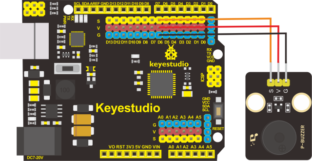
The G, V and S pins of passive buzzer are connected to G, V and D6 of the control Board.
Pin Connection Table |
|
|---|---|
Pin of the Buzzer |
Pin of Control Board |
G |
G |
V |
V |
S |
D6 |