4.3.1 LED Blink
4.3.1.1 Introduction
For starters and enthusiasts, LED Blink is a fundamental program. LED, the abbreviation of light emitting diodes, consists of Ga, As, P, N chemical compounds and so on. The LED can flash in diverse color by altering the delay time in the test code. When in control, power on GND and VCC, the LED will be on if S end is in high level; nevertheless, it will go off.
4.3.1.2 Component Knowledge
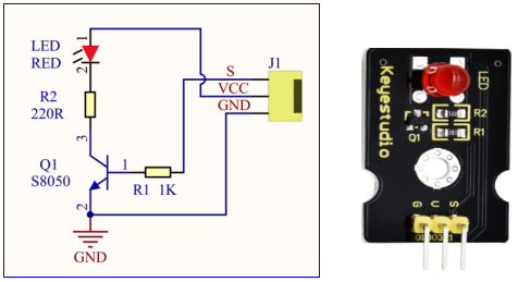
Parameters:
Control interface: digital port
Working voltage: DC 3.3-5V
Pin spacing: 2.54mm
LED display color: red
4.3.1.3 Components
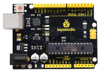
Keyestudio 4.0 development board *1 |
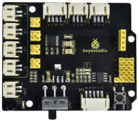
Keyestudio 8833 motor driver expansion board *1 |
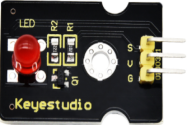
Red LED Module*1 |
|---|---|---|
|
|
|
3P F-F Dupont Wire*1 |
USB cable*1 |
|
|
|

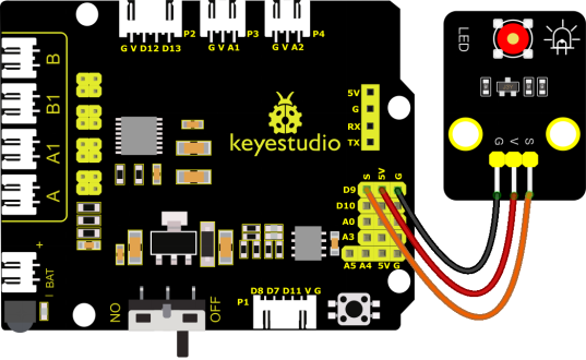
4.3.1.4 Wiring Diagrame
G, V and S of the LED module are connected to G, 5V and D9
⚠️ Attention: You do not need to disassemble the Smart Little Turtle Robot and re-connect the module. Here this disgram will be convenient for you to program and write code.
4.3.1.5 Test Code
/*
 keyestudio smart turtle robot
 lesson 1.1
 Blink
 http://www.keyestudio.com
*/
void setup()
{
  pinMode(9, OUTPUT);// initialize digital pin 9 as an output.
}

void loop() // the loop function runs over and over again forever
{
  digitalWrite(9, HIGH); // turn the LED on (HIGH is the voltage level)
  delay(1000); // wait for a second
  digitalWrite(9, LOW); // turn the LED off by making the voltage LOW
  delay(1000); // wait for a second
}
4.3.1.6 Test Result
Upload the code and power up. The LED connected to D9 will blink
4.3.1.7 Code Explanation
(1) pinMode(9,OUTPUT) - This function can denote that the pin is INPUT or OUTPUT.
(2) digitalWrite(9,HIGH) - When pin is OUTPUT, we can set it to HIGH(output 5V) or LOW(output 0V)
4.3.1.8 Code Explanation
We have succeeded in blinking LED. Next, let’s observe what will happen to the LED if we modify pins and delay time.
/*
 keyestudio smart turtle robot
 lesson 1.2
 delay
 http://www.keyestudio.com
*/
void setup()
{
  // initialize digital pin 11 as an output.
  pinMode(9, OUTPUT);
}
// the loop function runs over and over again forever
void loop()
{
  digitalWrite(9, HIGH); // turn the LED on (HIGH is the voltage level)
  delay(100); // wait for 0.1 second
  digitalWrite(9, LOW); // turn the LED off by making the voltage LOW
  delay(100); // wait for 0.1 second
}
The test result shows that the LED flashes faster. Therefore, pins and time delaying affect flash frequency.