4.3.11 Line Tracking Robot
4.3.11.1 Introduction
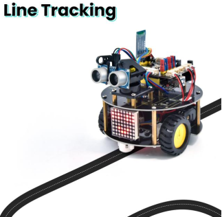
The previous projects are inclusive of the knowledge of multiple sensors and modules. Next, we will work on a little challenging task. Built on the working principle of the line tracking sensor we could make a
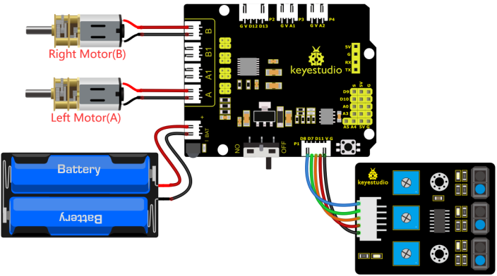
4.3.11.2 Wiring Diagram
G, V, S1, S2 and S3 of the line tracking sensor are connected to G(GND), V(VCC), D11, D7 and D8 of the sensor expansion board.
The power is connected to the BAT port
⚠️ Attention: You do not need to disassemble the Smart Little Turtle Robot and re-connect the module. Here this disgram will be convenient for you to program and write code.
4.3.11.3 Test Code
/*
keyestudio smart turtle robot
lesson 11
Tracking turtle
http://www.keyestudio.com
*/
int left_ctrl = 4;//define direction control pin of A motor
int left_pwm = 6;//define PWM control pin of A motor
int right_ctrl = 2;//define direction control pin of B motor
int right_pwm = 5;//define PWM control pin of B motor
int sensor_L = 11;//define the pin of left line tracking sensor
int sensor_M = 7;//define the pin of middle line tracking sensor
int sensor_R = 8;//define the pin of right line tracking sensor
int L_val,M_val,R_val;//define these variables
void setup() {
Serial.begin(9600);//start serial monitor and set baud rate to 9600
pinMode(left_ctrl,OUTPUT);//set direction control pin of A motor to OUTPUT
pinMode(left_pwm,OUTPUT);//set PWM control pin of A motor to OUTPUT
pinMode(right_ctrl,OUTPUT);//set direction control pin of B motor to OUTPUT
pinMode(right_pwm,OUTPUT);//set PWM control pin of B motor to OUTPUT
pinMode(sensor_L,INPUT);//set the pins of left line tracking sensor to INPUT
pinMode(sensor_M,INPUT);//set the pins of middle line tracking sensor to INPUT
pinMode(sensor_R,INPUT);//set the pins of right line tracking sensor to INPUT
}
void loop()
{
tracking(); //run main program
}
void tracking()
{
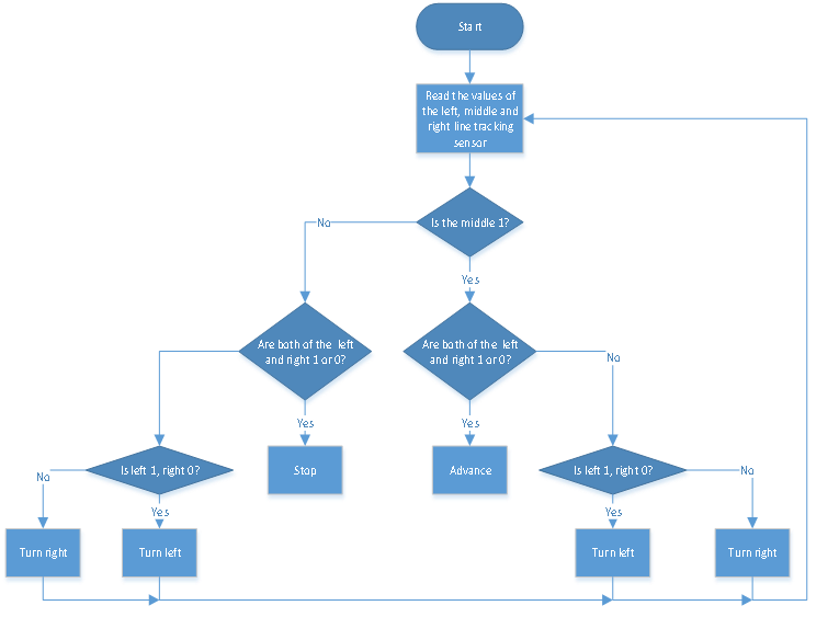
L_val = digitalRead(sensor_L);//read the value of left line tracking sensor
M_val = digitalRead(sensor_M);//read the value of middle line tracking sensor
R_val = digitalRead(sensor_R);//read the value of right line tracking sensor
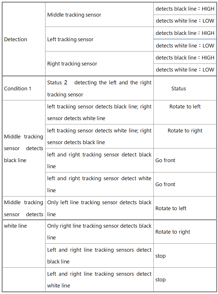
if(M_val == 1){//if the state of middle one is 1, which means detecting black line
if (L_val == 1 && R_val == 0) { //If a black line is detected on the left, but not on the right, turn left
left();
}
else if (L_val == 0 && R_val == 1) { //Otherwise, if a black line is detected on the right and not on the left, turn right
right();
}
else { //Otherwise,forward
front();
}
}
else { //No black lines detected in the middle
if (L_val == 1 && R_val == 0) { //If a black line is detected on the left, but not on the right, turn left
left();
}
else if (L_val == 0 && R_val == 1) { //Otherwise, if a black line is detected on the right and not on the left, turn right
right();
}
else { //Otherwise,stop
Stop();
}
}
}
void front()//define the status of going forward
{
digitalWrite(left_ctrl,HIGH);
analogWrite(left_pwm,100);
digitalWrite(right_ctrl,HIGH);
analogWrite(right_pwm,100);
}
void back()//define the state of going back
{
digitalWrite(left_ctrl,LOW);
analogWrite(left_pwm,155);
digitalWrite(right_ctrl,LOW);
analogWrite(right_pwm,155);
}
void left()//define the left-turning state
{
digitalWrite(left_ctrl,LOW);
analogWrite(left_pwm,155);
digitalWrite(right_ctrl,HIGH);
analogWrite(right_pwm,100);
}
void right()//define the right-turning state
{
digitalWrite(left_ctrl,HIGH);
analogWrite(left_pwm,100);
digitalWrite(right_ctrl,LOW);
analogWrite(right_pwm,155);
}
void Stop()//define the state of stop
{
digitalWrite(left_ctrl, LOW);
analogWrite(left_pwm,0);
digitalWrite(right_ctrl, LOW);
analogWrite(right_pwm,0);
}
4.3.11.4 Test Result
Uploading the code to the development board, powering up and turning the DIP switch to ON. The turtle car will walk along black lines.