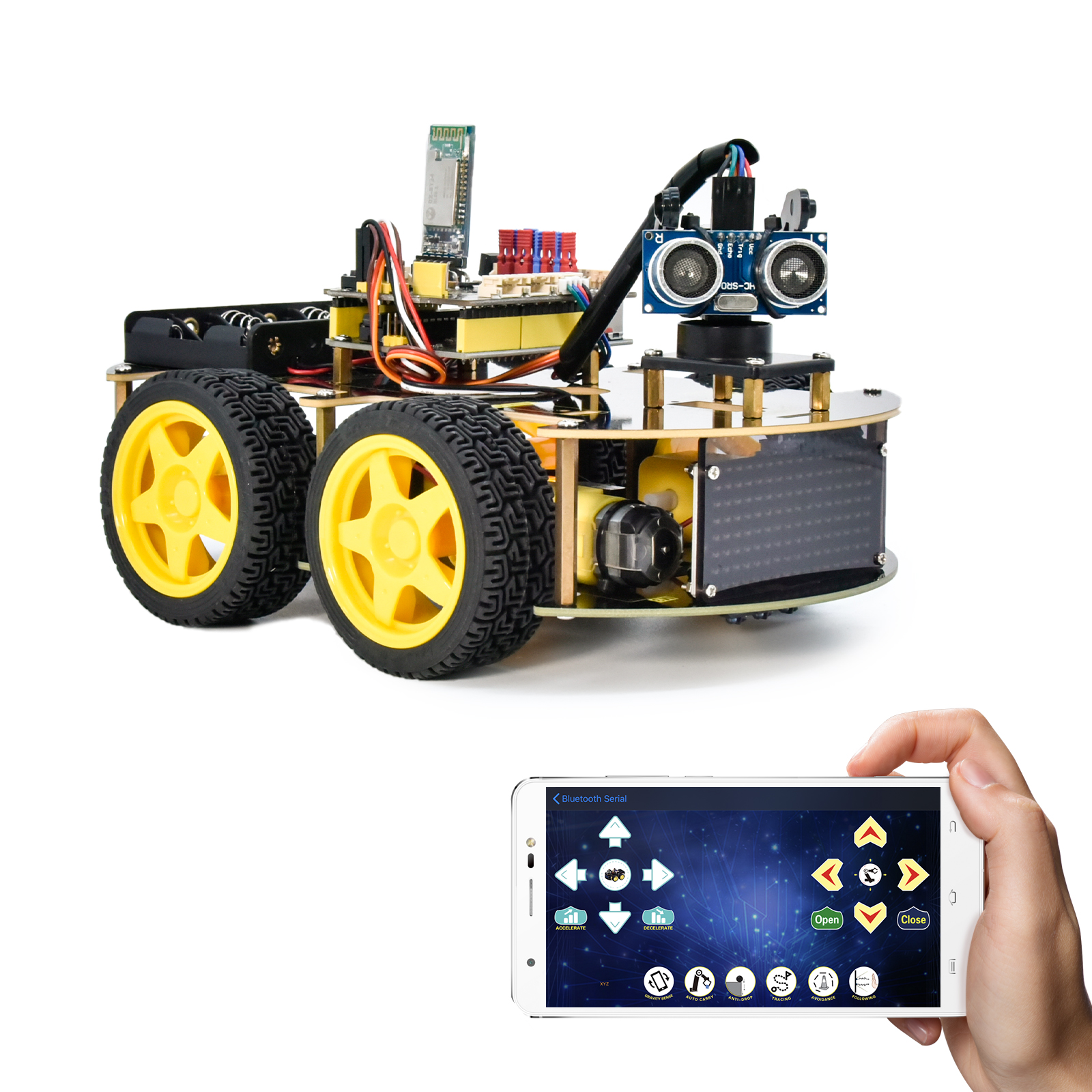
Project 16 Bluetooth Speed Control Smart Car
1.説明
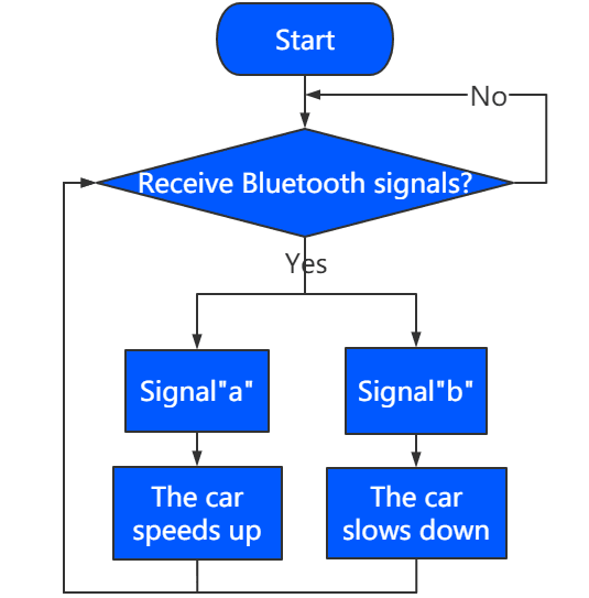
このプロジェクトでは、Bluetoothを使ってスマートカーの速度を調整します。変数speedsを定義し、それを変更することでスマートカーの速度を変えることができます。
2.フローチャート
3.配線図
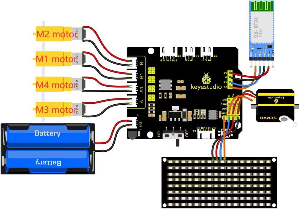
1). 8×8 LEDボードのGND、VCC、SDA、SCLは拡張ボードのG(GND)、V(VCC)、A4、A5に接続します。
2). BluetoothモジュールのRXD、TXD、GND、VCCはそれぞれ8833モーターシールドのTX、RX、G、5Vに接続します。BluetoothモジュールのSTATEとBRKピンは接続不要です。
3). サーボはG、V、A3に接続します。茶色の線はGnd(G)、赤色の線は5V(V)、オレンジ色の線はA3に接続します。
4). 電源はBATポートに接続します。
4.テストコード
注意: テストコードをアップロードする前にBluetoothモジュールを取り外す必要があります。そうしないとコードのアップロードに失敗します。コードのアップロードが成功したらBluetoothモジュールを接続してください。
//*******************************************************************************
/*
keyestudio 4wd BT Car
lesson 16
Bluetooth Speed Control Car
http://www.keyestudio.com
*/
#define SCL_Pin  A5  //クロックピンをA5に設定
#define SDA_Pin  A4  //データピンをA4に設定
//パターンのデータを格納する配列。自分で計算するかモジュールツールから取得可能
unsigned char start01[] = {0x01,0x02,0x04,0x08,0x10,0x20,0x40,0x80,0x80,0x40,0x20,0x10,0x08,0x04,0x02,0x01};
unsigned char front[] = {0x00,0x00,0x00,0x00,0x00,0x24,0x12,0x09,0x12,0x24,0x00,0x00,0x00,0x00,0x00,0x00};
unsigned char back[] = {0x00,0x00,0x00,0x00,0x00,0x24,0x48,0x90,0x48,0x24,0x00,0x00,0x00,0x00,0x00,0x00};
unsigned char left[] = {0x00,0x00,0x00,0x00,0x00,0x00,0x44,0x28,0x10,0x44,0x28,0x10,0x44,0x28,0x10,0x00};
unsigned char right[] = {0x00,0x10,0x28,0x44,0x10,0x28,0x44,0x10,0x28,0x44,0x00,0x00,0x00,0x00,0x00,0x00};
unsigned char STOP01[] = {0x2E,0x2A,0x3A,0x00,0x02,0x3E,0x02,0x00,0x3E,0x22,0x3E,0x00,0x3E,0x0A,0x0E,0x00};
unsigned char clear[] = {0x00,0x00,0x00,0x00,0x00,0x00,0x00,0x00,0x00,0x00,0x00,0x00,0x00,0x00,0x00,0x00};
unsigned char speed_a[] =
{0x00,0x40,0x20,0x10,0x08,0x04,0x02,0xff,0x02,0x04,0x08,0x10,0x20,0x40,0x00,0x00};
unsigned char speed_d[] =
{0x00,0x02,0x04,0x08,0x10,0x20,0x40,0xff,0x40,0x20,0x10,0x08,0x04,0x02,0x00,0x00};

int left_ctrl = 2;//グループBモーターの方向制御ピンを定義
int left_pwm = 5;//グループBモーターのPWM制御ピンを定義
int right_ctrl = 4;//グループAモーターの方向制御ピンを定義
int right_pwm = 6;//グループAモーターのPWM制御ピンを定義

int speeds = 150; //初期速度を150に設定

const int servopin = A3;//サーボのピンをA3に設定

char BLE_val;

void setup() {
  Serial.begin(9600);//
  pinMode(left_ctrl,OUTPUT);//グループBモーターの方向制御ピンをOUTPUTに設定
  pinMode(left_pwm,OUTPUT);//グループBモーターのPWM制御ピンをOUTPUTに設定
  pinMode(right_ctrl,OUTPUT);//グループAモーターの方向制御ピンをOUTPUTに設定
  pinMode(right_pwm,OUTPUT);//グループAモーターのPWM制御ピンをOUTPUTに設定
  servopulse(servopin,90);//サーボの角度を90度に設定
  delay(300);
  pinMode(SCL_Pin,OUTPUT);//クロックピンを出力に設定
  pinMode(SDA_Pin,OUTPUT);//データピンを出力に設定
  matrix_display(clear);
  matrix_display(start01); //start01の表現パターンを表示
}

void loop() {
   if(Serial.available()>0) {
    BLE_val = Serial.read();
    Serial.println(BLE_val);
  }
    switch(BLE_val)
    {
      case 'F' : car_front();
      matrix_display(clear);
      matrix_display(front);
      break;

      case 'B' : car_back();
      matrix_display(clear);
      matrix_display(back);
      break;

      case 'L' : car_left();
      matrix_display(clear);
      matrix_display(left);
      break;

      case 'R' : car_right();
      matrix_display(clear);
      matrix_display(right);
      break;

      case 'S' : car_Stop();
      matrix_display(clear);
      matrix_display(STOP01);
      break;

      case 'a' : speeds_a();
      matrix_display(clear);
      matrix_display(speed_a);
      break;

      case 'd' : speeds_d();
      matrix_display(clear);
      matrix_display(speed_d);
      break;
    }
}

void car_front()//前進状態を定義
{
  digitalWrite(left_ctrl,HIGH);
  analogWrite(left_pwm,(255-speeds));
  digitalWrite(right_ctrl,HIGH);
  analogWrite(right_pwm,(255-speeds));
}
void car_back()//後退状態を定義
{
  digitalWrite(left_ctrl,LOW);
  analogWrite(left_pwm,speeds);
  digitalWrite(right_ctrl,LOW);
  analogWrite(right_pwm,speeds);
}
void car_left()//左折状態を設定
{
  digitalWrite(left_ctrl, LOW);
  analogWrite(left_pwm, speeds);
  digitalWrite(right_ctrl, HIGH);
  analogWrite(right_pwm, (255-speeds));
}
void car_right()//右折状態を設定
{
  digitalWrite(left_ctrl, HIGH);
  analogWrite(left_pwm, (255-speeds));
  digitalWrite(right_ctrl, LOW);
  analogWrite(right_pwm, speeds);
}
void car_Stop()//停止状態を定義
{
  digitalWrite(left_ctrl,LOW);
  analogWrite(left_pwm,0);
  digitalWrite(right_ctrl,LOW);
  analogWrite(right_pwm,0);
}

void speeds_a() { //速度急増関数
  while (1) {
    Serial.println(speeds);  //速度情報を表示
    if (speeds < 255) { //最大255まで
      matrix_display(clear);
      matrix_display(speed_a);
      speeds++;
      delay(10);  //成長速度を調整
    }
    BLE_val = Serial.read();
    if (BLE_val == 'S') // 'S'を受信したら加速停止
    break;
  }
}
void speeds_d() { //速度減少関数
  while (1) {
    Serial.println(speeds);  //速度情報を表示
    if (speeds > 0) { //0まで減速
      matrix_display(clear);
      matrix_display(speed_d);
      speeds--;
      delay(10);    //減速速度を調整
    }
    BLE_val = Serial.read();
    if (BLE_val == 'S') // 'S'を受信したら減速停止
    break;
}
}

void servopulse(int servopin,int myangle)//サーボの動作角度
{
  for(int i=0; i<30; i++)
  {
    int pulsewidth = (myangle*11)+500;
    digitalWrite(servopin,HIGH);
    delayMicroseconds(pulsewidth);
    digitalWrite(servopin,LOW);
    delay(20-pulsewidth/1000);
  }
}

//この関数はドットマトリックス表示用
void matrix_display(unsigned char matrix_value[])
{
  IIC_start();  //データ転送開始条件を呼び出す関数
  IIC_send(0xc0);  //アドレス選択

  for (int i = 0; i < 16; i++) //パターンデータは16バイトです
  {
    IIC_send(matrix_value[i]); //パターンのデータを送信します
  }
  IIC_end();   //パターンデータ送信終了
  IIC_start();
  IIC_send(0x8A);  //表示制御、4/16パルス幅を選択
  IIC_end();
}
//データ送信が開始される条件
void IIC_start()
{
  digitalWrite(SDA_Pin, HIGH);
  digitalWrite(SCL_Pin, HIGH);
  delayMicroseconds(3);
  digitalWrite(SDA_Pin, LOW);
  delayMicroseconds(3);
  digitalWrite(SCL_Pin, LOW);
}
//データ送信の終了を示す
void IIC_end()
{
  digitalWrite(SCL_Pin, LOW);
  digitalWrite(SDA_Pin, LOW);
  delayMicroseconds(3);
  digitalWrite(SCL_Pin, HIGH);
  delayMicroseconds(3);
  digitalWrite(SDA_Pin, HIGH);
  delayMicroseconds(3);
}
//データ送信
void IIC_send(unsigned char send_data)
{
  for (byte mask = 0x01; mask != 0; mask <<= 1) //各バイトは8ビットで、最下位からビットごとにチェックします
  {
    if (send_data & mask) { //バイトの各ビットが1か0かに応じてSDA_Pinの高低レベルを設定します
      digitalWrite(SDA_Pin, HIGH);
    } else {
      digitalWrite(SDA_Pin, LOW);
    }
    delayMicroseconds(3);
    digitalWrite(SCL_Pin, HIGH); //クロックピンSCL_Pinを高レベルにしてデータ送信を停止します
    delayMicroseconds(3);
    digitalWrite(SCL_Pin, LOW); //クロックピンSCL_Pinを低レベルにしてSDAの信号を変化させます
  }
}
//*******************************************************************************
5.テスト結果
コードをV4.0ボードに正常にアップロードした後、配線図に従って配線を接続し、外部電源をオンにしてからDIPスイッチをONにします。APPとBluetoothをペアリングすると、APPでスマートカーを操作して動かすことができます。
 を押すと、車は加速し、
 を押すと、車は減速し、8*16 LEDボードにスマートカーの対応する状態パターンが表示されます。