Beetlebot 3 in 1 Robot for Pico

Download Resources:
Decription:
The Beetlebot smart robot, compatible with LEGO building blocks, is a STEM educational product which can automatically dodge obstacles, follow black lines and light to move. Besides, it has three cool forms such as the soccer robot, the siege robot, the handling robot. As for beginners, they cancreate whatever they want by LEGO building blocks.
Various improvements have been made on the Beetlebot car in comparison with other smart cars. It integrates a motor driver and a large number ofsensors and is easy to assemble. Beetlebot’s control core is today’s mainstream open source hardware, which allows it to implement low-cost programming learning programs.
Going forward, not only can it impart basic programming knowledge and AI application to children and the youth, but also it can cultivate their creativity, hands-on ability, problem-solving capability, interpersonal communication as well as teamwork ability. With this kit, you have a chance to experience soccer games using your own robots.
Features:
Compatible with LEGO building blocks: generate diverse forms with LEGO blocks and sensors
Three forms: a soccer robot, a siege engine, a handling robot
Various functions: Pictures display, atmosphere light control, line tracking, obstacle avoidance, light following , IR control and WIFI control.
Easy to build: embedded design on car body; wire up the car body with a few steps
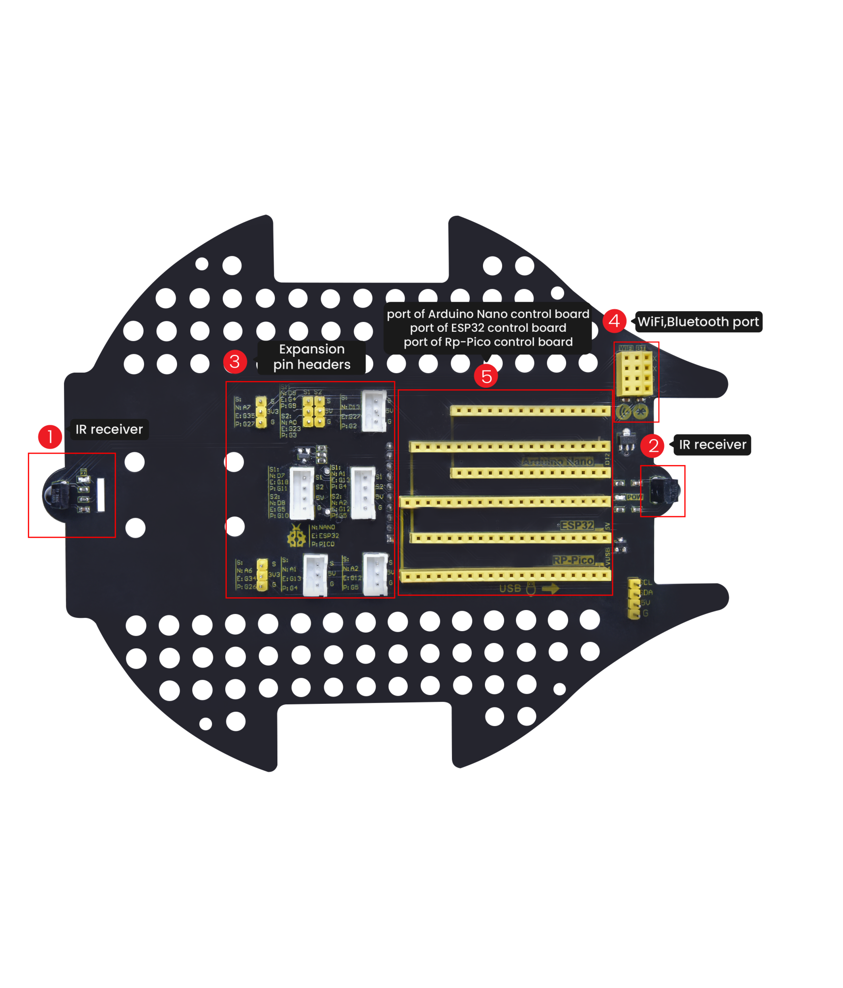
High compatibility: reserve ports for the Arduino Nano board and the ESP32 control board
Charging function: integrate a circuit for 18650 batteries, low-cost and effective
WiFi Control: adopt WiFi control, can finish tailor-made software development
App: compatible with Android and iOS systems, with aesthetic page and flexible control system
Specification:
Working voltage: 5V
Input voltage: 2.5V~4.2V (lithium battery)
Maximum output current: 3A
Maximum power consumption: 15W (T=80℃)
Motor speed: 5V 200 rpm / min
Motor drive form: dual H-bridge
Ultrasonic sensing angle: <15 degrees
Ultrasonic detection distance: 2cm-400cm
IR control distance: about 7 meters (measured)
Size: 176mm*137mm*130mm
Environmental protection attributes: ROHS
Kit List:
# |
Picture |
Name |
QTY |
|---|---|---|---|
|
Raspberry Pi Pico Board |
1 |
|
|
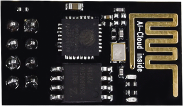
ESP8266 Wifi Module |
1 |
|
|
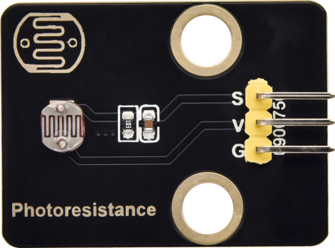
Keyestudio Photoresistor |
2 |
|
|
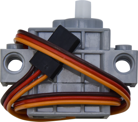
270° Servo |
1 |
|
|
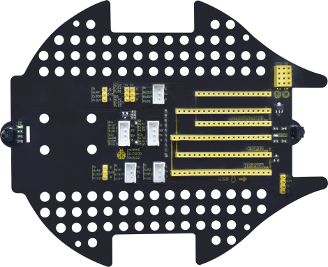
Keyestudio Development Board |
1 |
|
|
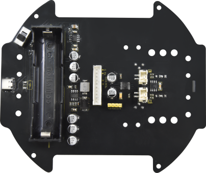
Keyestudio Driver Board |
1 |
|
|
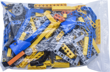
LEGO Bulk Lot |
1 |
|
|
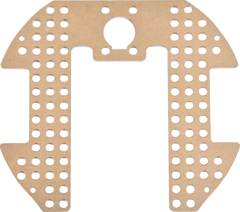
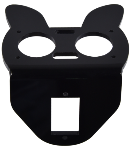
Acrylic Board |
1 |
|
|
MD0487 Acrylic Board for Ultrasonic Sensor |
1 |
|
|
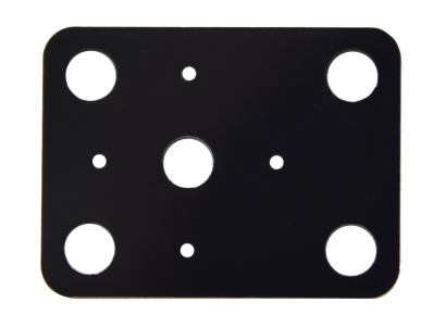
Acrylic Board for Servo |
1 |
|
|
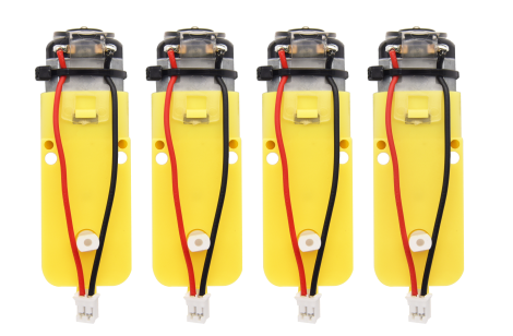
4.5V 200R Motor |
2 |
|
|
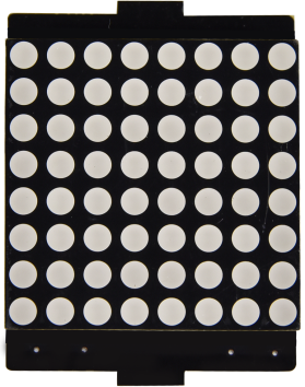
8*8 Dot Matrix Display |
1 |
|
|
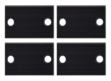
Aluminum Block |
2 |
|
|
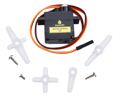
9G 180°Servo |
1 |
|
|
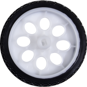
Car Wheel |
2 |
|
|
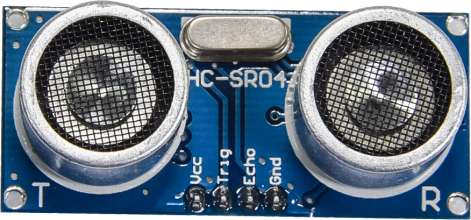
HC-SR04 Ultrasonic Sensor |
1 |
|
|
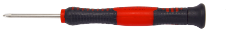
Screwdriver |
1 |
|
|
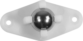
W420 Universal Wheel |
1 |
|
|
JMFP-4 17-Key Remote Control |
1 |
|
|
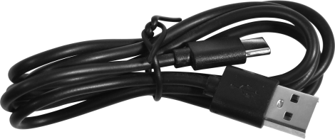
Black USB Cable |
1 |
|
|
Screwdriver |
1 |
|
|
3P F-F Dupont Wire |
2 |
|
|
4P F-F Dupont Wire |
1 |
|
|
HX2.54mm-4P Dupont Wire |
1 |
|
|
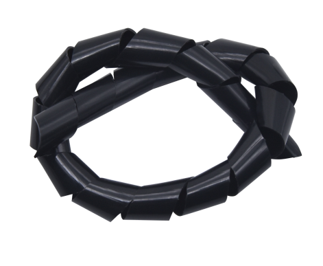
Winding Pipe |
1 |
|
|
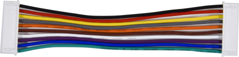
10P XH2.54 Dupont Wire |
1 |
|
|
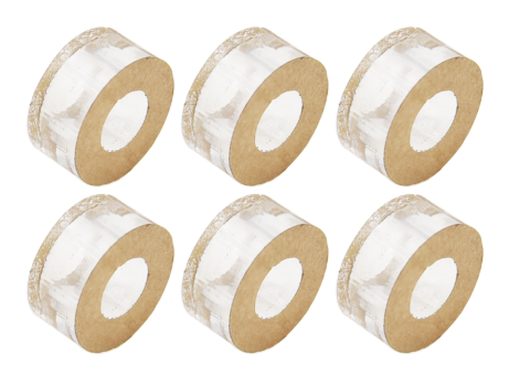
Acrylic Gasket |
6 |
|
|
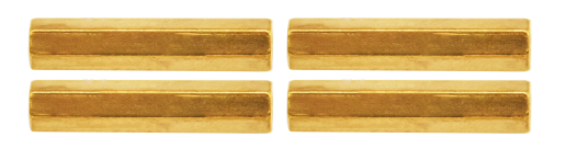
M3*40MM Dual Pass Copper Pillars |
4 |
|
|
M1.2*5MM Round Head Screws |
6 |
|
|
M1.4 Nuts |
6 |
|
|
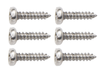
M1.4*10MM Round Head Screws |
6 |
|
|
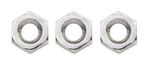
M2 Nuts |
3 |
|
|
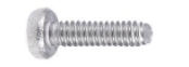
M2*8MM Round Head Screws |
3 |
|
|
M3*10MM Round Head Screws |
6 |
|
|
M3*6MM Round Head Screws |
11 |
|
|
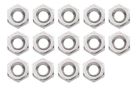
M3 Nuts |
9 |
|
|
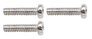
M3*30MM Round Head Screws |
4 |
|
|
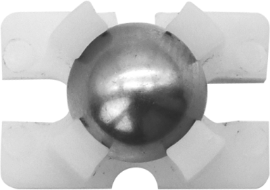
Soccer Ball |
1 |
|
|
W1515 Universal Wheel |
1 |
|
|
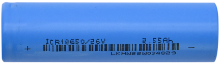
18650 Batteries KS3027F includes batteries KS3027 doesn’t conclude batteries |
1 |
|
|
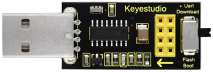
USB to ESP-01S WIFI Module Expansion Board |
1 |
|
|
USB Cable |
1 |
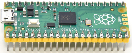


Raspberry Pi Pico Board:
1. Introduction:
Raspberry Pi Pico is a low-cost, high-performance microcontroller board with flexible digital interfaces. It integrates the RP2040 microcontroller chip designed by Raspberry Pi, with dual-core Arm Cortex M0+ processor running up to 133 MHz, embedded 264KB of SRAM and 2MB of on-board Flash memory, as well as 26 multi-function GPIO pins. For software development, either Raspberry Pi’s C/C++ SDK, or the MicroPython is available. In this tutorial, we provide you with corresponding tutorials in MicroPython.
2. Features:
※ RP2040 microcontroller chip designed by Raspberry Pi
※ Dual-core ARM Cortex M0+ processor, flexible clock running up to 133 MHz
※ 264kB of SRAM, and 2MB of on-board Flash memory
※ Castellated module allows soldering direct to carrier boards
※ USB 1.1 Host and device support
※ Low-power sleep and dormant modes
※ Drag & drop programming using mass storage over USB
※ 26 multi-function GPIO pins
※ 2×SPI, 2×I2C, 2×UART, 3×12-bit ADC, 16×controllable PWM channels
※ Accurate on-chip clock and timer
※ Temperature sensor
※ Accelerated floating point libraries on-chip
※ 8×Programmable IO (PIO) state machines for custom peripheral support
3. Parameters:
MCU: RP2040 microcontroller chip
CPU: Dual-core Arm Cortex-M0+ @ 133MHz
USB-to-serial chip: Built-in USB1.1 PHY host and device support, drag-and-drop download program through USB identification as mass storage
Working voltage: 3.0V-3.6V
Working current: average 80mA
Supply current: 500mA
External power supply: DC power supply is 6-12V (recommended 9V), USB power supply is 5V.
Flash Memory: Built-in 2MB
SRAM: Built-in 264KB
Integrated crystal oscillator: 12MHz
**Dimensions: **
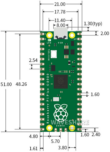
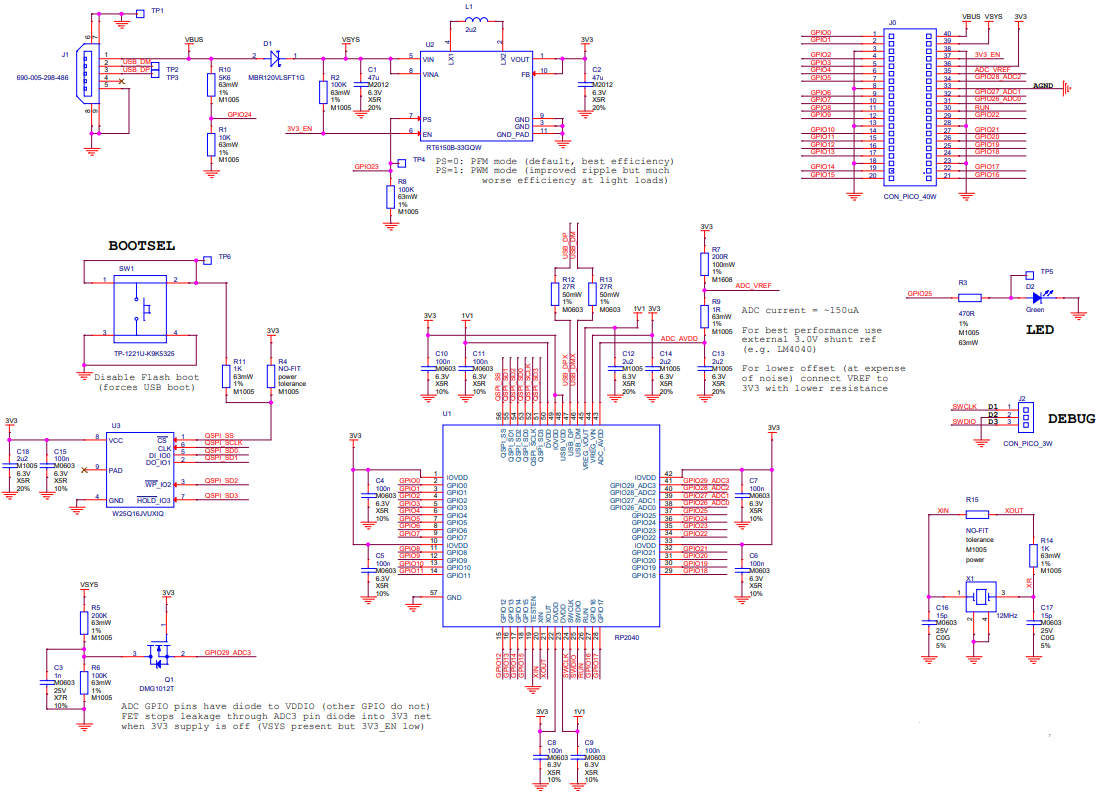
4. Schematic Diagram:
5. Pin Out
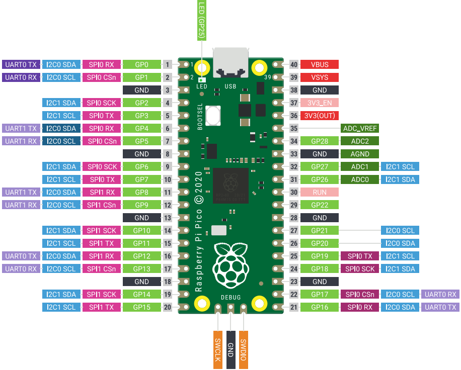
PIN |
FUNCTION |
|---|---|
GND |
Ground pin |
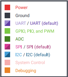
Power |
VBUS(microUSB voltage), VSYS(2-5VDC input voltage), 3V3(3.3V output voltage) 3V3_EN(Enables Pico) |
System Control |
run (enable or disable the RP2040 microcontroller or reset) |
ADC |
Raspberry Pi Pico has a total of 5 ADCs with a resolution of 12 bits, namely ADC0 (GP26), ADC1 (GP27), ADC2 (GP28), ADC3 (GP29), ADC4. |
PWM |
Raspberry Pi Pico has 16 PWM channels,each of channel can control frequency and duty cycle.GPIO pin is switched to PWM |
UART |
Two UART: UART0,UART1 |
I2C |
Two types of I2C: I2C0 I2C1 |
SPI |
Two types of SPI:SPI0,SPI1 |
Debugging |
used in debugging code |
Related information: https://datasheets.raspberrypi.com/pico/pico-datasheet.pdf
PCB Board:
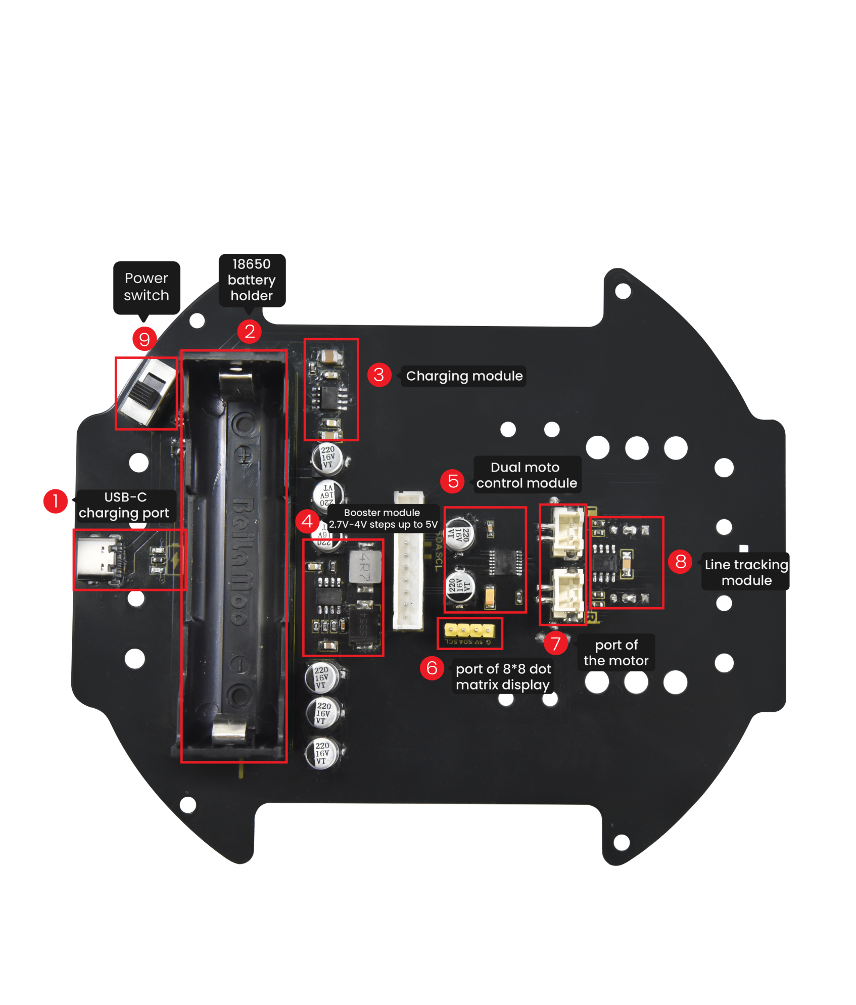 Note: Switch the DIP switch to OFF before removing or installing the battery.