Python Tutorial
Preparation for Python
Before we start building a project, we need to do some preparations first, which is so important that we can’t skip it.
Install Thonny
Thonny is a free and open source software platform with small size, simple interface, simple operation and rich functions. It is a Python IDE suitable for beginners. In this tutorial, we use this IDE to develop a Raspberry Pi Pico. Thonny supports multiple operating systems including Windows, Mac OS, Linux.
Download Thonny
Enter the website: https://thonny.org to download the latest version of Thonny.
Thonny open-source code library: https://github.com/thonny/thonny
Please follow the instructions on the official website or click the link below to download and install. (Please select the appropriate option based on your operating system.)
[System](javascript:;) |
Download link |
|---|---|
MAC OS: |
https://github.com/thonny/thonny/releases/download/v3.2.7/thonny-3.2.7.pkg |
Windows: |
https://github.com/thonny/thonny/releases/download/v3.2.7/thonny-3.2.7.exe |
Linux: |
latest version Binary bundle for PC (Thonny+Python): bash <(wget -O - https://thonny.org/installer-for-linux) With pip: pip3 install thonny Distro packages (may not be the latest version): Debian, Rasbian, Ubuntu, Mint and others: sudo apt install thonny Fedora: sudo dnf install thonny |

Install Thonny on Windows
The downloaded Thonny icon is as follows.
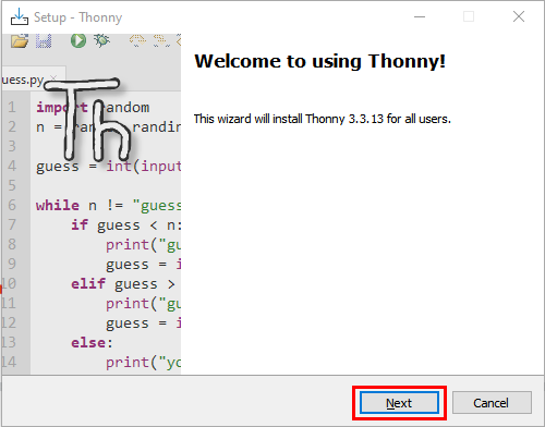
Double-click “Thonny-3.3.13.exe”. The following dialog box is displayed. I choose“ ”to operate. You can also select“
 ” to operate.

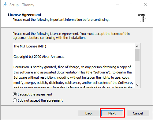
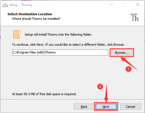
If you are not familiar with computer software installation, click “Next” until the installation is complete.
If you want to change the route of installing Thonny,just click“Browse…”to select a new route and click “OK”.
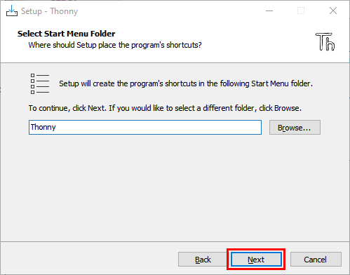
If you don’t want to change the route of installing Thonny, just click “Next”and then click“Next”again.
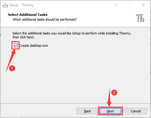
Select “Create Desktop Icon”. Thonny software will generate a shortcut on your desktop for you to open Thonny software later.
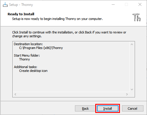
Click “Install”
Wait for a while but don’t click Cancel

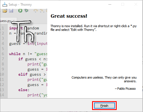
Once we see the following screen, Thonny software has been successfully installed. Click “Finish”.
If we select “Create Desktop Icon” during the installation, the following icon will be displayed on the desktop.

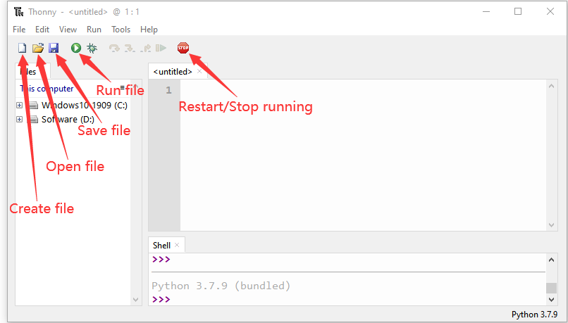
Basic configuration of Thonny software
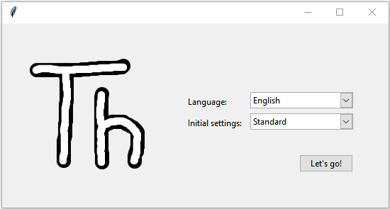
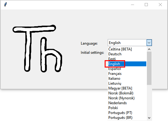
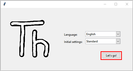
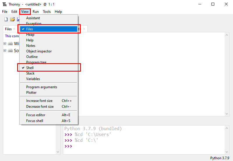
Double-click the desktop icon of Thonny software, we can see the following interface, and we can also choose the language and initial settings. Once set, click “Let’s Go!”
Select“View”→“File”和“Shell”

Update Micropython firmware
To run MicroPython programs on Raspberry Pi Pico, we first need to burn a firmware into Raspberry Pi Pico.
Why do we need to update the firmware?
The Raspberry Pi Pico can be programmed in both C and MicroPython, and which is shipped without MicroPython firmware, which we need to download before we can program with MicroPython.
Note: MicroPython Firmware only needs to be downloaded once and does not need to be downloaded again when programming with MicroPython. If we have downloaded the.uf2 firmware written in C, it will be overwritten, so the next time we use MicroPython, we need to update our Raspberry Pi Pico firmware by following the steps.
Download the Micropython Firmware
Method1: Raspberry Pi Pico official website:https://www.raspberrypi.com/documentation/microcontrollers/
Click the link above, we can see the following interface:

Scroll the mouse and we can see the following again:

Click MicroPython(Getting Started MicroPython) to go to the firmware download page.

Method 2: By clicking on the download link: https://micropython.org/download/rp2-pico/rp2-pico-latest.uf2, we can download directly.
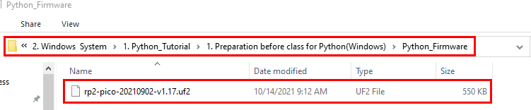
Method 3: If we can’t download it due to network problems or other reasons, we can use the.uf2 file we prepared, which is located in the following file path.
The procedures for burning MicroPython firmware
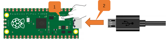
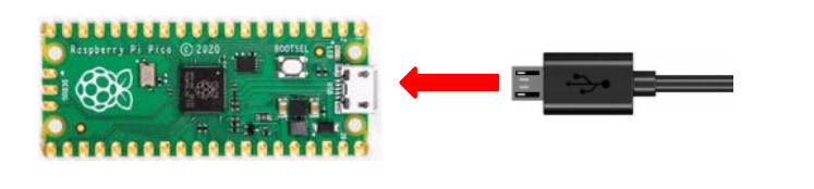
① Connect one end of the microUSB cable to the USB port of our computer.
② Long press the white button on the “Raspberry Pi Pico” (BOOTSEL). The Raspberry Pi Pico is then connected to the computer via the microUSB wire.
③ Release the button, when the connection is successful, open [Device Manager] on our computer, the computer will automatically recognize the removable disk (RPI-RP2), as shown below:

④ Copy the file (RP2-Pico-20210902-v1.17.uf2) to a removable disk (RPI-rp2) and wait for it to complete, just like copying the file to a USBflash drive.

⑤ Raspberry Pi Pico automatically restarts after the firmware is burned. After that, we can run Micropython.
Thonny connects to Raspberry Pi Pico
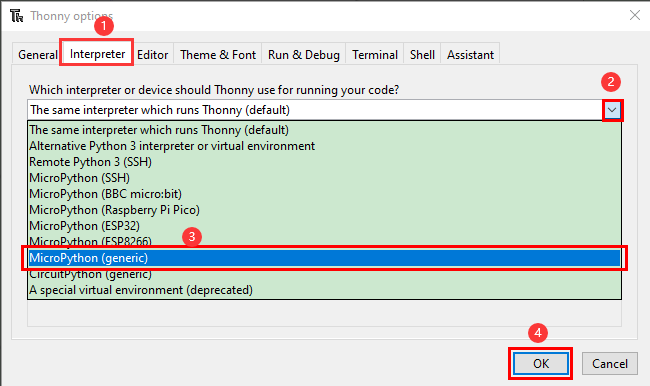
1.Open Thonny, click“Run”and select“Select interpreter…”

2.Select“Micropython (generic)”or“Micropython (Raspberry Pi Pico)”How to select“Micropython(generic)”? As follows:
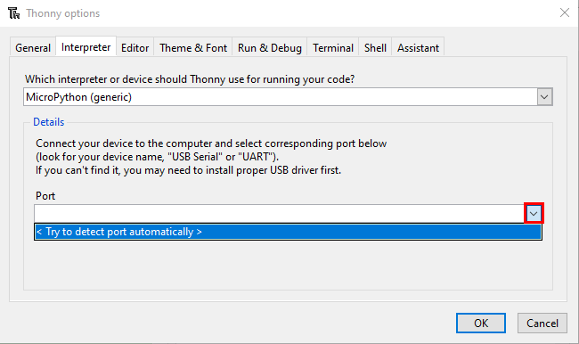
Select USB-Serial (COMx). The COMx number may be different on different PCS. Just make sure we select “USB-Serial (COMx)”.
How to determine which port does the Raspberry Pi Pico communicate with our computer?
Step 1: When our Raspberry Pi Pico is not connected to the computer, open Thonny software, click “Run”, select “Select Interpreter”, the dialog will pop up, click “Port”, we can view the currently connected port, as shown in the picture below:
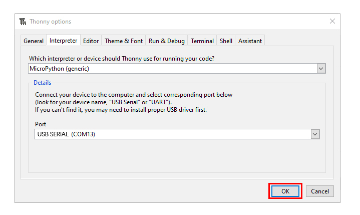
Step 2: Close the dialog box. Connect Raspberry Pi Pico to our computer, click “Run” again and select “Select Interpreter”. Click “Port” in the window that is displayed to view the current port. Now add another port, so this port is used to communicate with the computer.

Select“Micropython(generic)”and port,and click“OK”.
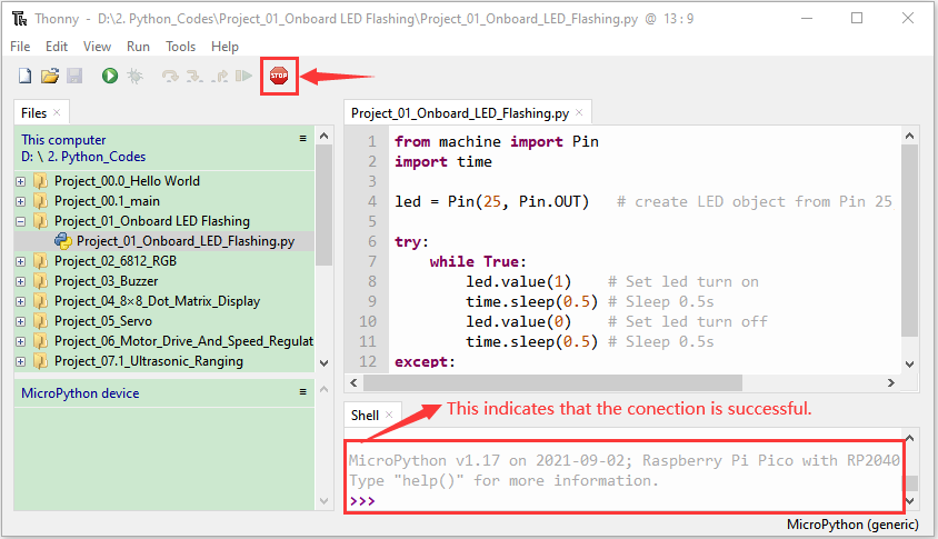
When the following message is displayed on Thonny, then the Thonny successfully connects to the Raspberry Pi Pico.

So far, all the preparations have been made.
Projects:
Project 1: Onboard LED Flashing
Description:
Raspberry Pi Pico has an onboard LED,which is a GP25 pin attached to the Raspberry Pi Pico. In this project, we will learn the effect of making the onboard LED blink.
Knowledge:

3.Wiring Up
In this project, Raspberry Pi Pico is connected to a computer using a USB cable.
4. Test Code
Raspberry Pi Pico onboard LEDS are controlled by THE GP25, which lights up when the GP25 output is high. When the output is low, the LED lights turn off.
The code used in this project is saved at KS3027 Keyestudio Beetlebot 3 in 1 Robot for Pico STEM Education Cart \ 2.Python Tutorials\2.python_codes. We can move the code anywhere. For example, we can save the code in Disk(D) with the path D:\2.Python_Codes.

Code running online:
Open “Thonny” and click “This computer” → “D:” → “2. Python_Codes” →”Project_01_Onboard LED Flashing”.

Open the“Project_01_Onboard LED Flashing”folder, and double-click “Project_01_Onboard_LED_Flashing. py” to open it. As shown below:

from machine import Pin import time led = Pin(25, Pin.OUT) # create LED object from Pin 25, Set Pin 25 to output try: while True: led.value(1) # Set led turn on time.sleep(0.5) # Sleep 0.5s led.value(0) # Set led turn off time.sleep(0.5) # Sleep 0.5s except: pass |
Make sure Raspberry Pi Pico is connected to the computer. Click “Stop/Restart Backend” and see what the “Shell” window displays.
Click “Run Current Script” and the code starts executing, and what you see is: Raspberry Pi Pico’s LED starts flashing. Or press Ctrl+C or click to exit the program.

Note: This is the code that runs online. If you disconnect the USB cable and restart Raspberry Pi Pico, the LEDS on Raspberry Pi Pico stop flashing. The following information will be displayed in the “Shell” window of Thonny software:

Code to run offline (upload code to Raspberry Pi Pico) :
Ensure that the Raspberry Pi Pico is connected to the computer and click
.

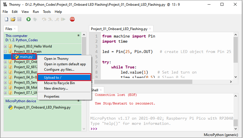
As shown in the following figure, right-click the file“Project_01_Onboard_LED_Flashing. py” and choose“Upload to/”to upload the code to Raspberry Pi Pico.
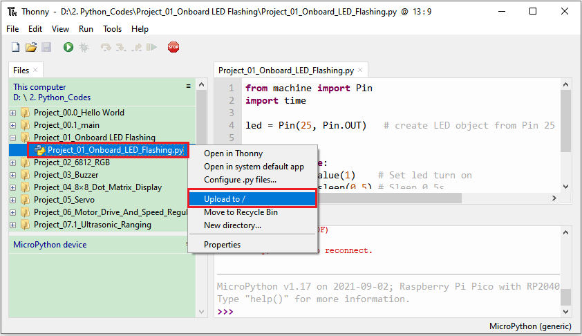
Upload main.py in the same way.

Disconnect the USB cable from the Raspberry Pi Pico and reconnect, and the Raspberry Pi Pico’s LED flashes repeatedly.
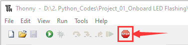
Note: The code here runs offline. If you want to Stop running offline and display the information in the “Shell” window, simply click
in Thonny software.
Project 2: 6812 RGB
Description:
There are 4 RGB LEDs, which can be widely used in the decoration of buildings, bridges, roads, gardens, courtyards and so on by colors adjustment.
In this experiment, we will demonstrate different lighting effects with them.
Knowledge:
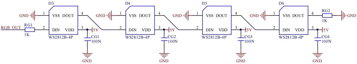
SK6812RGB: There are four RGB LEDS on the expansion board of the car. It can be seen from the schematic diagram that these four RGBLED are all connected in series. Under the condition of sufficient voltage and current, hundreds of RGB leds can be connected. Every RGBLED is an independent pixels, each pixel is consist of R, G, B three primary colors, which can realize the class of 256 and complete 16777216 colours of whole true color display.At the same time, the pixel contains internal intelligent digital interface data latch signal shaping amplifier drive circuit and the built-in signal shaping circuit, effectively ensure the pixel point light color height consistency .
Test Code
The SK6812RGB of the PCB board is controlled by the GPIO 13 of the Raspberry Pi Pico.
The code is saved in the KS3027 Keyestudio Beetlebot 3 in 1 Robot for Pico STEM Education \ 2.Python Tutorials\ 2.python_codes.
We can move the code anywhere. For example, we can save the code in Disk(D) with the path D:\2.Python_Codes.

Open the “Thonny” software, click “This computer”→”D:”→”2.Python_Codes”→”Project_02_6812_RGB” .
Select “neopixel.py” and right-click and select “Upload to /”. Then the “neopixel.py” will be uploaded to the Raspberry Pi Pico, then left-click “Project_02_6812_RGB.py”


#Import Pin, neopiexl and time modules. import time from machine import Pin from neopixel import myNeopixel #Define the number of pin and LEDs connected to neopixel. NUM_LEDS = 4 np = myNeopixel(NUM_LEDS, 13) red = (255, 0, 0) green = (0, 255, 0) blue = (0, 0, 255) white = (255, 255, 255) close = (0, 0, 0) COLORS = [red, green, blue, white, close] np.brightness(150) #brightness: 0 ~ 255 while True: for color in COLORS: np.fill(color[0], color[1], color[2]) np.show() time.sleep(0.5) |
Test Result:
Ensure that the Raspberry Pi Pico is connected to the computer and click
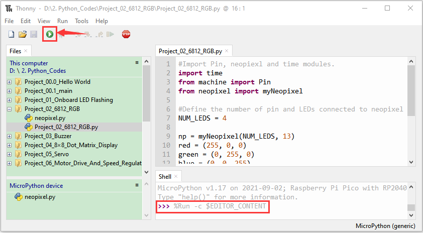
Click “Run Current Script”, the code starts to execute, we can see that the 4 RGB LED on the CAR PCB board will show red, green, blue, white then go off, the cycle goes on.

Project 3: Play Music
Description:
There is a power amplifier component on the expansion board, which is often used to play music and serve as an external amplifying device for music playback devices.
In this experiment, we use the speaker amplifier component to play music.
2. Knowledge:
Power amplifier modules(equivalent to a passive buzzer) don’t have internal oscillation circuits.
The power amplifier module can chime sounds with different frequency when power it up.
3. Test Code
The speaker module of the PCB board is controlled by the GPIO 12 of the Raspberry Pi Pico.
The code is saved in the KS3027 Keyestudio Beetlebot 3 in 1 Robot for Pico STEM Education \ 2.Python Tutorials\ 2.python_codes.
We can move the code anywhere. For example, we can save the code in Disk(D) with the path D:\2.Python_Codes.
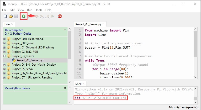
Open the “Thonny” software, click “This computer”→”D:”→”2.Python_Codes”→”Project_03_Buzzer” .
Double-click“Project_03_Buzzer.py”

from machine import Pin import time #Initialize the passive buzzer buzzer = Pin(12,Pin.OUT) #Simulate two different frequencies while True: #Output 500HZ frequency sound for i in range(80): buzzer.value(1) time.sleep(0.001) buzzer.value(0) time.sleep(0.001) #Output 250HZ frequency sound for i in range(100): buzzer.value(1) time.sleep(0.002) buzzer.value(0) time.sleep(0.002) |
4. Test Result:
Ensure that the Raspberry Pi Pico is connected to the computer and click.

Click “Run Current Script”, the code starts to execute, we will see the car PCB speaker amplifier components start to beep. Press“Ctrl+C”or click to exit the program.
Project 4: 8*8 Dot Matrix
1.Description:
Composed of LED emitting tube diodes, the 8*8 LED dot matrix are applied widely to public information display like bus station, advertising screen, bank window screen, stop screen and parking system, etc, by controlling LED to show words, pictures and videos, etc.
In this experiment, the 8*8 dot matrix screens will be used to display patterns.
2.Knowledge:
8*8 dot matrix screen: The LED dot matrix screen according to LED light color can be divided into monochrome, two-color, three-color lights, etc., which can display red, yellow, green and even true color. According to the number of LED, it can be divided into 4×4, 8×8, 16×16 and other different types. Here we see how this works by using a monochrome 8×8 lattice screen.
Different dot matrix screens are packaged differently. The 8×8 dot matrix screens are composed of 64 LED lights in 8 rows and 8 columns, and the inner structure of 8×8 dot matrix is shown below.
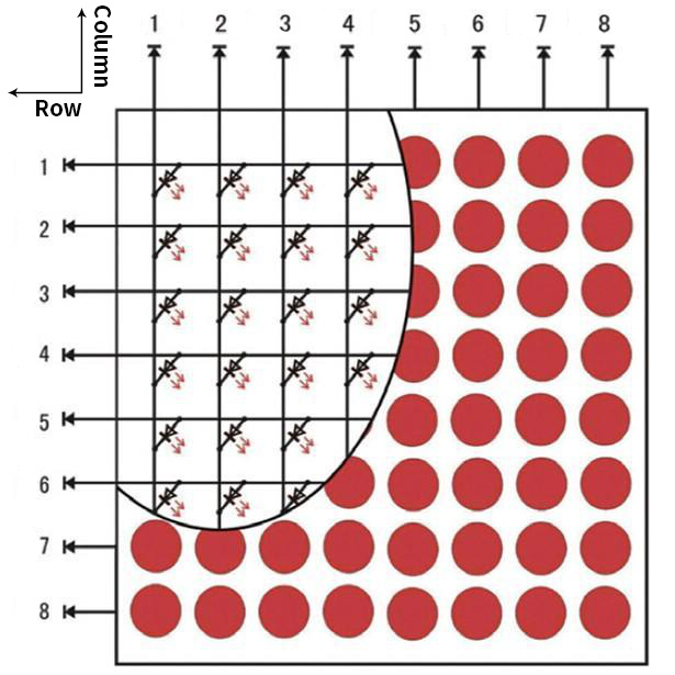
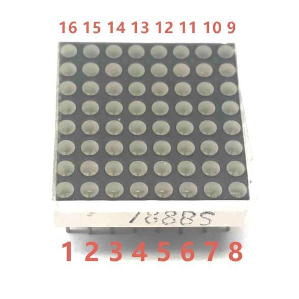
Every LED is installed on the cross point of row line and column line. When the voltage on a row line increases, and the voltage on the column line reduces, the LED on the cross point will light up. The 8×8 dot matrix has 16 pins. Put the silk-screened side down and the numbers are 1,-8, 9- 16 in anticlockwise order as marked below.
The definition inner pins are shown below:
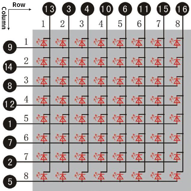
For instance, to light up the LED on row 1 and column 1, we should increase the voltage of pin 9 and reduce the voltage of pin 13.
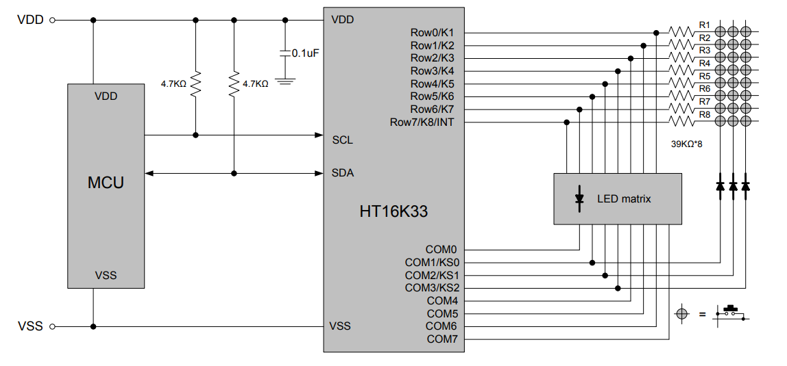
HT16K33 8X8 Dot Matrix: The above introduced the principle of 8*8 dot matrix, which requires up to 16 single chip pins to control it . It’s a waste of resources and time. Here we use a chip that drives the dot matrix screen: HT16K33. HT16K33 is a memory mapping and multi-function LED controller driver chip. Using HT16K33 chip to drive an 8*8 dot matrix, only the I2C communication port of MCU is used to control the dot matrix, which greatly saves the resources of MCU. The following figure is the working principle diagram of HT16K33 chip.
3. Specification:
Input voltage: 5V
Rated input frequency: 400KHZ
Input power: 2.5W
Input current: 500mA
4. Introduction for Modulus Tool
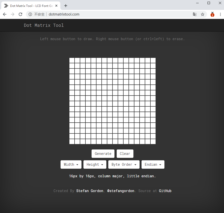
The principle of dot matrix and drive has been introduced,but how is the content displayed on the dot matrix come? Is there a relatively simple method? Here to introduce a lattice modulus tool, this tool is used online, link: http://dotmatrixtool.com/#
Let us see how to use it together now.
①Open the link to enter the following page.
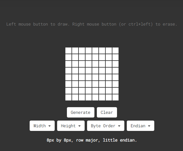
②The dot matrix is 8*8 in this project. So set the height to 8, width to 8; as shown below.
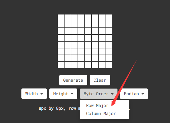
③Click Byte order to select Row major
Click Endian to select Big Endian(MSB)
④ Generate the pattern into hexadecimal data
As shown below, the left button of the mouse is for selection while the right is for canceling. Thus you could use them to draw the pattern you want, then click Generate, to yield the hexadecimal data needed.

The generated hexadecimal code(0x00, 0x66, 0x00, 0x00, 0x18, 0x42, 0x3c, 0x00) is what will be displayed, so we need to save it for next procedure.
Wiring up:
8*8 Dot matrix display |
PCB Board |
G |
G |
5V |
5V |
SDA |
SDA |
SCL |
SCL |
Test Code
The 8*8 dot matrix is controlled by the GPIO20 (SDA) and GPIO21(SCL) of the Raspberry Pi Pico motherboard.
Go to the folder KS3027 Keyestudio Beetlebot 3 in 1 Robot for Pico STEM Education\2. Python Tutorials\2.Python_Codes, You can save the code anywhere. For example, we save the code in the Disk(D)
Open“Thonny”, click “This computer”→“D:”→“2.Python_Codes”→“Project_04_8×8_Dot_Matrix_Display” .
Select“ht16k33_matrix.py”and“matrix_fonts.py”, right-click“Upload to/” and upload them to the Pico board, then double-click“Project_04_8×8_Dot_Matrix_Display.py”


from machine import Pin,I2C import time import json import matrix_fonts from ht16k33_matrix import ht16k33_matrix ## Tool To Make Sprites https://gurgleapps.com/tools/matrix #i2c config clock_pin = 21 data_pin = 20 bus = 0 i2c_addr_left = 0x70 use_i2c = True def scan_for_devices(): i2c = machine.I2C(bus,sda=machine.Pin(data_pin),scl=machine.Pin(clock_pin)) devices = i2c.scan() if devices: for d in devices: print(hex(d)) else: print('no i2c devices') if use_i2c: scan_for_devices() left_eye = ht16k33_matrix(data_pin, clock_pin, bus, i2c_addr_left) def show_char(left): if use_i2c: left_eye.show_char(left) def scroll_message(font,message='hello',delay=0.05): #Scrolling display left_message = ' ' + message right_message = message + ' ' length=len(right_message) char_range=range(length-1) for char_pos in char_range: right_left_char=font[right_message[char_pos]] right_right_char=font[right_message[char_pos+1]] left_left_char=font[left_message[char_pos]] left_right_char=font[left_message[char_pos+1]] for shift in range(8): left_bytes=[0,0,0,0,0,0,0,0] right_bytes=[0,0,0,0,0,0,0,0] for col in range(8): left_bytes[col]=left_bytes[col]|left_left_char[col]<<shift left_bytes[col]=left_bytes[col]|left_right_char[col]>>8-shift; right_bytes[col]=right_bytes[col]|right_left_char[col]<<shift right_bytes[col]=right_bytes[col]|right_right_char[col]>>8-shift; if use_i2c: left_eye.show_char(left_bytes) time.sleep(delay) while True: show_char(matrix_fonts.textFont1['A']) #Show the letter A time.sleep(1) show_char(matrix_fonts.textFont1['B']) time.sleep(1) show_char(matrix_fonts.textFont1['C']) time.sleep(1) scroll_message(matrix_fonts.textFont1, 'Hello World') |
Test Result:
Ensure that the Raspberry Pi Pico is connected to the computer, and click.

Click “Run Current Script”, the code starts to execute, and we will see that the 8*8 dot matrix display character “A” 1S, display character “B” 1S, display character “C” 1S, then scroll display string “Hello World”, repeat. Press Ctrl+C or click Stop/Restart Backend to exit the program.

Project 5: Servo Rotation
Description:
There are two servos on the car. We take the servo connected to pin D9 as an example.
The servo is a motor that can rotate very accurately. It has been widely applied to toy cars, remote control helicopters, airplanes, robots and other fields. In this project, we will use the Nano motherboard to control the servo to spin.
Knowledge:

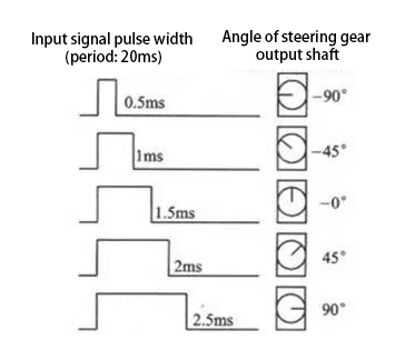
Servo motor is a position control rotary actuator. It mainly consists of a housing, a circuit board, a core-less motor, a gear and a position sensor. Its working principle is that the servo receives the signal sent by MCU or receiver and produces a reference signal with a period of 20ms and width of 1.5ms, then compares the acquired DC bias voltage to the voltage of the potentiometer and obtain the voltage difference output.
When the motor speed is constant, the potentiometer is driven to rotate through the cascade reduction gear, which leads that the voltage difference is 0, and the motor stops rotating. Generally, the angle range of servo rotation is 0° –180 °
The rotation angle of servo motor is controlled by regulating the duty cycle of PWM (Pulse-Width Modulation) signal. The standard cycle of PWM signal is 20ms (50Hz). Theoretically, the width is distributed between 1ms-2ms, but in fact, it’s between 0.5ms-2.5ms. The width corresponds the rotation angle from 0° to 180°. But note that for different brand motors, the same signal may have different rotation angles.
In general, servo has three lines in brown, red and orange. The brown wire is grounded, the red one is a positive pole line and the orange one is a signal line.
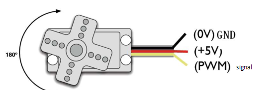
Wire up:
Servo |
PCB Board |
Brown |
G |
Red |
5V |
Orange |
S1(GPIO9) |
Test Code 1:
The servo of the ultrasonic sensor is controlled by the GPIO9 of the Pico board.
Go to the folder KS3027 Keyestudio Beetlebot 3 in 1 Robot for Pico STEM Education\2. Python Tutorials\2.Python_Codes, You can save the code anywhere. For example, we save the code in the Disk(D).
Open“Thonny”, click “This computer”→“D:”→“2.Python_Codes”→“Project_05.1_Servo_Rotate.py”

from machine import Pin, PWM import time #Define GPIO9’s output frequency as 50Hz and assign them to PWM. pwm = PWM(Pin(9)) pwm.freq(50) ''' #Duty cycle corresponding to steering gear Angle 0°----2.5%----1638 45°----5%----3276 90°----7.5%----4915 135°----10%----6553 180°----12.5%----8192 ''' #steering gear Angle are fit to its duty cycle. angle_0 = 1638 angle_45 = 3276 angle_90 = 4915 angle_135 = 6553 angle_180 = 8192 while True: pwm.duty_u16(angle_0) time.sleep(1) pwm.duty_u16(angle_45) time.sleep(1) pwm.duty_u16(angle_90) time.sleep(1) pwm.duty_u16(angle_135) time.sleep(1) pwm.duty_u16(angle_180) time.sleep(1) |
Test Result 1:
Ensure that the Raspberry Pi Pico is connected to the computer, and click.

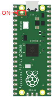
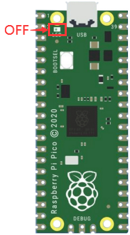
Place batteries in the battery holder and turn the power switch to the
ON endand then click “Run Current Script”. We will see that servo rotate
0°→45°→90°→135°→180° in loop way. Press”Ctrl+C” or click
to exit the program.
Test Code 2:
Go to the folder KS3027 Keyestudio Beetlebot 3 in 1 Robot for Pico STEM Education\2. Python Tutorials\2.Python_Codes, You can save the code anywhere. For example, we save the code in the Disk(D).
Open“Thonny”and click This computer”→“D:”→“2.Python_Codes”→“Project_05_Servo”
Select myservo.py and right-click Upload to /
Then double-click Project_05.2_Servo_Sweep.py


from myservo import Servo import time servo=Servo(9) servo.ServoAngle(0) time.sleep_ms(1000) try: while True: for i in range(0, 180, 1): servo.ServoAngle(i) time.sleep_ms(15) for i in range(180, 0, -1): servo.ServoAngle(i) time.sleep_ms(15) except: servo.deinit() |
Test Result 2:
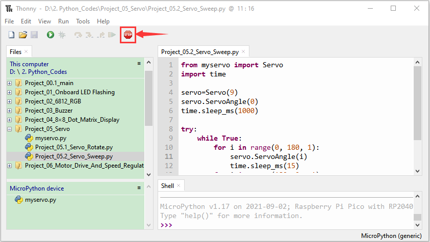
Connect the Pico board to your computer and click“Stop/Restart backend”
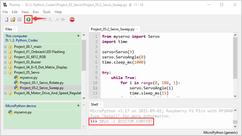
Place batteries in the battery holder and turn the power switch to the ON end and click “Run Current Script”, we will see that servo rotate from 0° to 180°then from 180° to 0°constantly. Press “Ctrl+C” or click”Stop/Restart Backend” to exit the program.
Project 6: Motor Driving and Speed Control
Description:
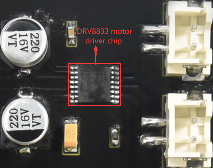
There are many ways to drive motors. This car uses the most commonly used DRV8833 motor driver chip, which provides a dual-channel bridge electric driver for toys, printers and other motor integration applications.
In this experiment, we use the DRV8833 motor driver chip on the expansion board to drive the two DC motors, and demonstrate the effect of forward, backward, left-turning, and right-turning.
Knowledge:
DRV8833 motor driver chip: Dual H-bridge motor driver with current control function, can drive two DC motors, one bipolar stepper motor, solenoid valve or other inductive loads. Each H-bridge includes circuitry to regulate or limit winding current.
An internal shutdown function with a fault output pin is used for over-current and short circuit protection, under-voltage lockout and over-temperature. A low-power sleep mode is also added. Let’s take a look at the schematic diagram of the DRV8833 motor driver chip driving two DC motors:
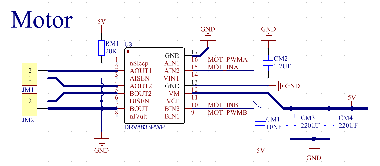
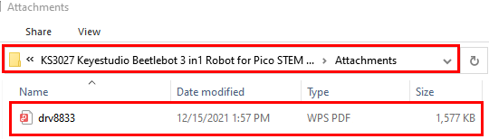
If you want to get insight to it, you can check the specification of this chip. Just browse it in the“Attachments”folder.
3. Specification:
Input voltage of logic part: DC 5V
Input voltage of driving part : DC 5V
Working current of logic part: <30mA
Operating current of driving part: <2A
Maximum power dissipation: 10W (T=80℃)
Motor speed: 5V 200 rpm / min
Motor drive form: dual H-bridge drive
Control signal input level: high level 2.3V<Vin<5V, low level -0.3V<Vin<1.5V
Working temperature: -25~130℃
4. Drive the car to move
From the above diagram, the direction pin of the left motor is GPIO15; the speed pin is GPIO17; GPIO14 is the direction pin of the right motor; and GPIO16 is speed pin.
PWM drives the robot car. The PWM value is in the range of 0-65535. The more the PWM value is set, the faster the rotation of the motor.
Function |
GPIO15 |
GPIO17(PWM)(PWM)(PWM) |
Left motor |
GPIO14 |
GPIO16(PWM)(PWM)(PWM) |
Right motor |
forward |
1 |
50000 |
clockwise |
1 |
50000 |
clockwise |
Go back |
0 |
10000 |
anticlockwise |
0 |
10000 |
anticlockwise |
Turn left |
0 |
50000 |
anticlockwise |
1 |
32768 |
clockwise |
Turn right |
1 |
32768 |
clockwise |
0 |
50000 |
anticlockwise |
Stop |
0 |
0 |
stop |
0 |
0 |
stop |
5. Test Code
Go to the folder KS3027 Keyestudio Beetlebot 3 in 1 Robot for Pico STEM Education\2. Python Tutorials\2.Python_Codes, You can save the code anywhere. For example, we save the code in the Disk(D)
Open “Thonny”, click “This computer”→“D:”→“2.Python_Codes”→“Project_06_Motor_Drive_And_Speed_Regulation”

from machine import Pin,PWM import time # right wheel pin1=Pin(14,Pin.OUT) pin2=PWM(Pin(16)) pin2.freq(50) # left wheel pin3=Pin(15,Pin.OUT) pin4=PWM(Pin(17)) pin4.freq(50) # As a function of the car going forward. def car_forward(): pin1.value(0) pin2.duty_u16(50000) pin3.value(0) pin4.duty_u16(50000) # As a function of the car going backwards. def car_back(): pin1.value(1) pin2.duty_u16(10000) pin3.value(1) pin4.duty_u16(10000) # As a function of the car going left. def car_left(): pin1.value(0) pin2.duty_u16(50000) pin3.value(1) pin4.duty_u16(32768) # As a function of the car going right. def car_right(): pin1.value(1) pin2.duty_u16(32768) pin3.value(0) pin4.duty_u16(50000) # As a function of the car stopping. def car_stop(): pin1.value(0) pin2.duty_u16(0) pin3.value(0) pin4.duty_u16(0) try: while True: car_forward() #Car ahead time.sleep(2) # delay 2s car_back() # Car goes back time.sleep(2) car_left() # Car to the left time.sleep(2) car_right() # Car to the right time.sleep(2) car_stop() # Car stop time.sleep(2) except: pass |
Test Result
Ensure that the Raspberry Pi Pico is connected to the computer, and click“Stop/Restart backend”.

Place batteries in the battery holder and turn the power switch to the ON end and click “Run Current Script”
The car moves forward for 2 seconds, backward for 2 seconds, turns left for 2 seconds, turns right for 2 seconds, stops for 2 seconds, constantly. Press Ctrl+C or click
to exit the program.

Project 7: Ultrasonic Sensor
There is an ultrasonic sensor on the car. It is a very affordable distance-measuring sensor.
The ultrasonic sensor sends a high-frequency ultrasonic signal that human hearing can’t hear. When encountering obstacles, these signals will be reflected back immediately. After receiving the returned information, the distance between the sensor and the obstacle will be calculated by judging the time difference between the transmitted signal and the received signal. It is mainly used for object avoidance and ranging in various robotics projects.
Project 7.1: Ultrasonic Ranging
1.Description:
In this experiment, we use an ultrasonic sensor to measure distance and print the data on a serial monitor.
2. Knowledge:
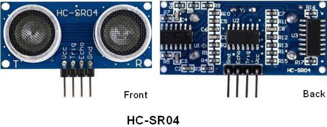
The HC-SR04 ultrasonic sensor uses sonar to determine distance to an object like what bats do. It offers excellent non-contact range detection with high accuracy and stable readings in an easy-to-use package. It comes complete with ultrasonic transmitter and receiver modules.
In front of the ultrasonic sensor are two metal cylinders, and these are converters, which converts mechanical energy into electrical signals. In ultrasonic sensors, there are transmitting converters and receiving converters.
The transmitting converters transform electrical signals into ultrasonic pulses and the receiving converters transform reflected ultrasonic pulses back to electrical signals. If we look at the back of the ultrasonic sensor, we’ll see an IC behind the transmitter, which controls the transmitting converter. There is also an IC behind the receiving converter, which is a quad operational amplifier that amplifies the signal generated by the receiving converter into a signal large enough to transmit to the Arduino.
3.Sequence Diagram
The sequence diagram of HC-SR04 is shown below. In order to begin measurement, the Trig of the SR04 must receive a high pulse (5V) of at least 10uS,which will trigger the sensor to emit eight cycles of 40kHz ultrasonic pulse and wait for the reflected ultrasonic pulse. When the sensor detects an ultrasonic wave from the receiver, it sets the echo pin to high (5V) and delay to one cycle (width), proportional to the distance. To get the distance, measure the width of the Echo pin.
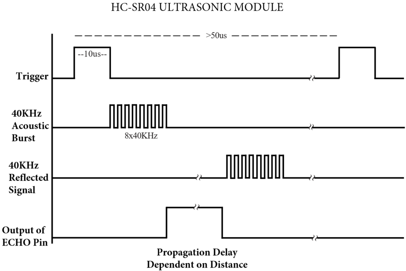
Time=Echo pulse width, unit: us
Distance(cm)=time/ 58
Distance(inch)=time/ 148
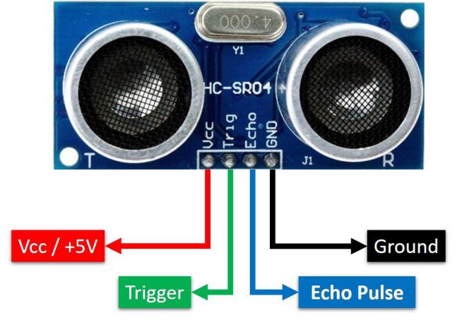
The HC-SR04 ultrasonic sensor has four pins: Vcc, Trig, Echo and GND.
The Vcc pin provides power generating ultrasonic pulses and is connected to Vcc/+5V. The GND pin is grounded/GND.
The Trig pin is where the Arduino sends a signal to start the ultrasonic pulse. The Echo pin is where the ultrasonic sensor sends information about the duration of the ultrasonic pulse stroke to the Arduino control board.
4.Wiring Up
Ultrasonic Sensor |
PCB Board |
Vcc |
5V |
Trig |
S2(GPIO10) |
Echo |
S1(GPIO11) |
Gnd |
G |
Test Code
The pin Trig and Echo of the ultrasonic sensor are controlled by the GPIO10 and GPIO11 of the pico board.
Go to the folder KS3027 Keyestudio Beetlebot 3 in 1 Robot for Pico STEM Education\2. Python Tutorials\2.Python_Codes, You can save the code anywhere. For example, we save the code in the Disk(D).
Click Thonny and click This computer”→“D:”→“2.Python_Codes”→“Project_07.1_Ultrasonic_Ranging”
Double-click Project_07.1_Ultrasonic_Ranging.py

from machine import Pin import time #Define the control pins of the ultrasonic ranging module. trigPin=Pin(10,Pin.OUT,0) echoPin=Pin(11,Pin.IN,0) #Set the speed of sound. soundVelocity=340 distance=0 #Subfunction getSonar() is used to start the Ultrasonic Module to begin measurements, #and return the measured distance in centimeters. In this function, first let trigPin #send 10us high level to start the Ultrasonic Module. Then use pulseIn() to read #the Ultrasonic Module and return the duration time of high level. #Finally, the measured distance according to the time is calculated. def getSonar(): trigPin.value(1) time.sleep_us(10) trigPin.value(0) while not echoPin.value(): pass pingStart=time.ticks_us() while echoPin.value(): pass pingStop=time.ticks_us() pingTime=time.ticks_diff(pingStop,pingStart) distance=pingTime*soundVelocity//2//10000 return int(distance) #Delay for 2 seconds and wait for the ultrasonic module to stabilize, #Print data obtained from ultrasonic module every 500 milliseconds. time.sleep_ms(2000) while True: time.sleep_ms(500) print('Distance: ',getSonar(),'cm' ) |
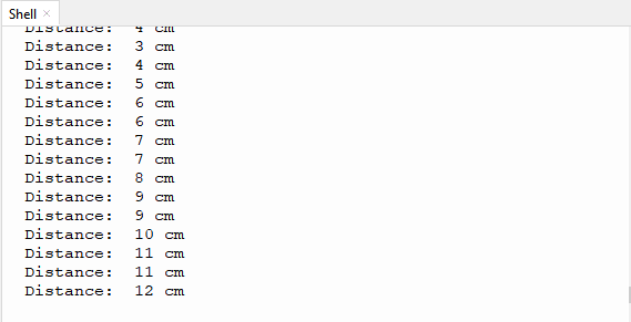
Test Result
Ensure the Raspberry Pi Pico is connected to the computer,and click“Stop/Restart backend”.

Place batteries in the battery holder and turn the power switch to the ON end and click “Run Current Script”
We will see that the distance value between the ultrasonic sensor and the object will be printed in the “Shell” window under Thonny IDE. Press “Ctrl+C” or click “Stop/Restart Backend” to exit the program.

Project 7.2: Light Following
1.Description:
In the above experiments, we have learned about the 8*8 dot matrix, motor drivers and speed regulation, ultrasonic sensors, servos and other hardware. In this experiment, we will combine them to create a follow car with the ultrasonic sensor. The can can follow an object to move through measuring distance.
2. Working Principle:
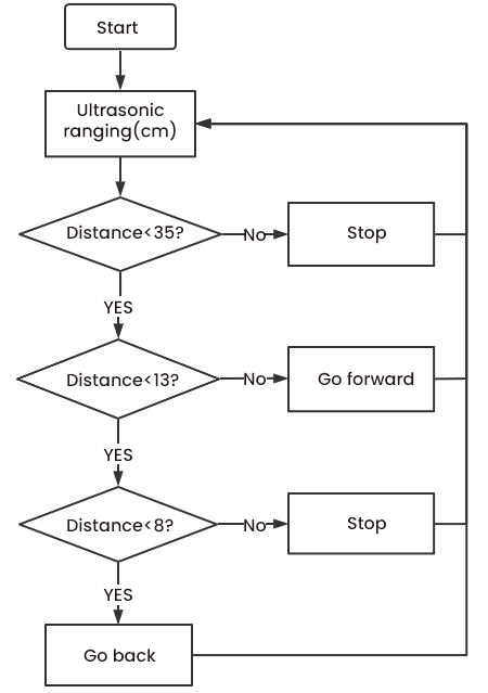
Detection |
Detect the front distance |
Distance(unit:cm) |
Condition 1 |
Distance<8 |
|
State |
Go back(set PWM to 100) |
|
Condition 2 |
8≤distance<13 |
|
State |
stop |
|
Condition 3 |
13≤distance<35 |
|
State |
Go forward(set PWM to 100) |
|
Condition 4 |
distance≥35 |
|
State |
stop |
3.Flow Chart:
4.Test Code
Go to the folder KS3027 Keyestudio Beetlebot 3 in 1 Robot for Pico STEM Education\2. Python Tutorials\2.Python_Codes, You can save the code anywhere. For example, we save the code in the Disk(D)
Click Thonny and click This computer”→“D:”→“2.Python_Codes”→“Project_07.2_Follow_Me
Double-click Project_07.2_Follow_Me.py

from machine import Pin, PWM import time ''' #Duty cycle corresponding to steering gear Angle 0°----2.5%----1638 45°----5%----3276 90°----7.5%----4915 135°----10%----6553 180°----12.5%----8192 ''' #Define GPIO9’s output frequency as 50Hz and its duty cycle as 4915, and assign them to PWM. servoPin = PWM(Pin(9)) servoPin.freq(50) servoPin.duty_u16(4915) time.sleep(1) #Set the pin and sound speed of the ultrasonic sensor trigPin=Pin(10,Pin.OUT,0) echoPin=Pin(11,Pin.IN,0) soundVelocity=340 distance=0 # right wheel pin1=Pin(14,Pin.OUT) pin2=PWM(Pin(16)) pin2.freq(50) # left wheel pin3=Pin(15,Pin.OUT) pin4=PWM(Pin(17)) pin4.freq(50) # As a function of the car going forward. def car_forward(): pin1.value(0) pin2.duty_u16(30000) pin3.value(0) pin4.duty_u16(30000) # As a function of the car going backwards. def car_back(): pin1.value(1) pin2.duty_u16(30000) pin3.value(1) pin4.duty_u16(30000) # As a function of the car stopping. def car_stop(): pin2.deinit() pin4.deinit() pin1.value(0) pin2.duty_u16(0) pin3.value(0) pin4.duty_u16(0) #Subfunction getSonar() is used to start the Ultrasonic Module to begin measurements, #and return the measured distance in centimeters. In this function, first let trigPin #send 10us high level to start the Ultrasonic Module. Then use pulseIn() to read #the Ultrasonic Module and return the duration time of high level. #Finally, the measured distance according to the time is calculated. def getSonar(): trigPin.value(1) time.sleep_us(10) trigPin.value(0) while not echoPin.value(): pass pingStart=time.ticks_us() while echoPin.value(): pass pingStop=time.ticks_us() pingTime=time.ticks_diff(pingStop,pingStart) distance=pingTime*soundVelocity//2//10000 time.sleep_ms(10) return int(distance) while True: Distance=getSonar() #Get the distance measured by ultrasound. print(Distance) #Send a pulse to calculate the distance in centimeters and print the result. if Distance<8: #If the distance is less than 8 pin2=PWM(Pin(16)) pin2.freq(50) pin4=PWM(Pin(17)) pin4.freq(50) car_back() #Car goes back elif Distance>=8 and Distance<13: #If the distance is greater than or equal to 8, it's less than 13. car_stop() # Car stop elif Distance>=13 and Distance<35: #If the distance is greater than or equal to 13, it's less than 35. pin2=PWM(Pin(16)) pin2.freq(50) pin4=PWM(Pin(17)) pin4.freq(50) car_forward() #Car ahead else: car_stop() |
5. Test Result:
Ensure the Raspberry Pi Pico is connected to the computer,and click“Stop/Restart backend”.
Place batteries in the battery holder and turn the power switch to the ON end and click “Run Current Script”.
We will see that the car can move with the movement of obstacles in front of it. Press Ctrl+C or click Stop/Restart Backend to exit the program.


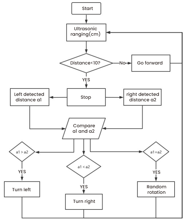
Project 7.3: Dodge Obstacles
1.Description:
In the last experiment, we made an ultrasonic following car. In fact, using the same hardware, we only needed to change one test code to change it into an obstacle avoidance car. But how to achieve it? Of course, it is also achieved through the range of ultrasonic sensors. The obstacle in front of the robot is detected by ultrasonic sensor, and then the direction of the robot movement is obtained according to the data.
2. Working Principle:
8*8 Dot matrix display |
|||
Set servo to 90° |
|||
loop |
Detect the distance away from the obstacle(unit: cm) |
||
Condition 1 |
State |
||
0<distance<10 |
Stop |
||
Show the“stop”pattern |
|||
Set the servo to 180° |
Distance away form the obstacle:a1(unit:cm) |
||
Set the servo to 0° |
Distance away form the obstacle:a2(unit:cm) |
||
Condition 2 |
State |
||
a1<a2 |
Car turns right(set PWM to 200) |
||
show“turning right”pattern |
|||
Set servo to 90° |
|||
a1≥a2 |
Turn left(set PWM to 200) |
||
display“left turning”pattern |
|||
Set servo to 90° |
|||
distance≥10 |
The 8*8 dot matrix display shows“going forward”pattern |
||
Go forward(set PWM to 200) |
3. Flow Chart:
4. Test Code
Go to the folder KS3027 Keyestudio Beetlebot 3 in 1 Robot for Pico STEM Education\2. Python Tutorials\2.Python_Codes, You can save the code anywhere. For example, we save the code in the Disk(D)
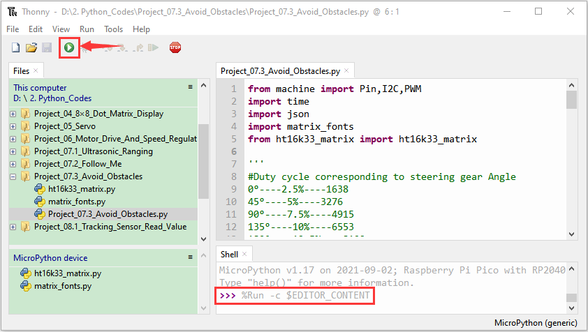
Open“Thonny” and click This computer”→“D:”→“2.Python_Codes”→“Project_07.3_Avoid_Obstacles”,
Select “ht16k33_matrix.py”and“matrix_fonts.py” and click“Upload to /”.
Then double-click“Project_07.3_Avoid_Obstacles.py”


from machine import Pin,I2C,PWM import time import json import matrix_fonts from ht16k33_matrix import ht16k33_matrix ''' #Duty cycle corresponding to steering gear Angle 0°----2.5%----1638 45°----5%----3276 90°----7.5%----4915 135°----10%----6553 180°----12.5%----8192 ''' #Define GPIO9’s output frequency as 50Hz and its duty cycle as 4915, and assign them to PWM. servoPin = PWM(Pin(9)) servoPin.freq(50) servoPin.duty_u16(4915) time.sleep(1) #Set the pin and sound speed of the ultrasonic sensor. trigPin=Pin(10,Pin.OUT,0) echoPin=Pin(11,Pin.IN,0) soundVelocity=340 distance=0 # right wheel pin1=Pin(14,Pin.OUT) pin2=PWM(Pin(16)) pin2.freq(50) # left wheel pin3=Pin(15,Pin.OUT) pin4=PWM(Pin(17)) pin4.freq(50) # As a function of the car going forward. def car_forward(): pin1.value(0) pin2.duty_u16(20000) pin3.value(0) pin4.duty_u16(20000) # As a function of the car going left. def car_left(): pin1.value(0) pin2.duty_u16(20000) pin3.value(1) pin4.duty_u16(40000) # As a function of the car going right. def car_right(): pin1.value(1) pin2.duty_u16(40000) pin3.value(0) pin4.duty_u16(20000) # As a function of the car stopping. def car_stop(): pin2.deinit() pin4.deinit() pin1.value(0) pin2.duty_u16(0) pin3.value(0) pin4.duty_u16(0) #Subfunction getSonar() is used to start the Ultrasonic Module to begin measurements, #and return the measured distance in centimeters. In this function, first let trigPin #send 10us high level to start the Ultrasonic Module. Then use pulseIn() to read #the Ultrasonic Module and return the duration time of high level. #Finally, the measured distance according to the time is calculated. def getSonar(): trigPin.value(1) time.sleep_us(10) trigPin.value(0) while not echoPin.value(): pass pingStart=time.ticks_us() while echoPin.value(): pass pingStop=time.ticks_us() pingTime=time.ticks_diff(pingStop,pingStart) distance=pingTime*soundVelocity//2//10000 time.sleep_ms(10) return int(distance) ## Tool To Make Sprites https://gurgleapps.com/tools/matrix #i2c config clock_pin = 21 data_pin = 20 bus = 0 i2c_addr_left = 0x70 use_i2c = True def scan_for_devices(): i2c = machine.I2C(bus,sda=machine.Pin(data_pin),scl=machine.Pin(clock_pin)) devices = i2c.scan() if devices: for d in devices: print(hex(d)) else: print('no i2c devices') if use_i2c: scan_for_devices() left_eye = ht16k33_matrix(data_pin, clock_pin, bus, i2c_addr_left) def show_char(left): if use_i2c: left_eye.show_char(left) while True: Distance=getSonar() #Get the distance measured by ultrasound. if Distance>0 and Distance<10: #If the distance is greater than 0, it's less than 10. car_stop() # Car stop show_char(matrix_fonts.textFont1['!']) #Show the punctuation ! time.sleep(0.2) servoPin.duty_u16(8192) time.sleep(0.3) a1=getSonar() time.sleep(0.2) servoPin.duty_u16(1638) time.sleep(0.3) a2=getSonar() time.sleep(0.2) if a1>a2: pin2=PWM(Pin(16)) pin2.freq(50) pin4=PWM(Pin(17)) pin4.freq(50) car_left() show_char(matrix_fonts.textFont1['>']) servoPin.duty_u16(4915) time.sleep(0.3) show_char(matrix_fonts.textFont1['^']) else: pin2=PWM(Pin(16)) pin2.freq(50) pin4=PWM(Pin(17)) pin4.freq(50) car_right() show_char(matrix_fonts.textFont1['<']) servoPin.duty_u16(4915) time.sleep(0.3) show_char(matrix_fonts.textFont1['^']) else: pin2=PWM(Pin(16)) pin2.freq(50) pin4=PWM(Pin(17)) pin4.freq(50) car_forward() #Car ahead show_char(matrix_fonts.textFont1['^']) |
Ensure the Raspberry Pi Pico is connected to the computer,and click“Stop/Restart backend”.
Place batteries in the battery holder and turn the power switch to the ON end and click “Run Current Script”
We will see that the car can avoid obstacles automatically when we put some obstacles around it. Press Ctrl+C or click Stop/Restart Backend to exit the program.

Project 8: Line Tracking Sensor
There are two IR line tracking sensors on the car. They are actually two pairs of ST188L3 infrared tubes and used to detect black and white lines. In this project, we will make a line tracking car.
Project 8.1: Reading Values
1.Description:
In this experiment, we use ST188L3 infrared tubes to detect black and white lines, then print the data on the serial monitor.
2. Knowledge:
Infrared line tracking:
The IR line tracking sensor boasts a pair of ST188L3 infrared tubes,which has an infrared emitting diode and a receiver tube. When the emitting diode emits an infrared signal then received by the receiving tube after being reflected by the white object. Once the receiving tube receives the signal, the output terminal will output a low level (0); when the infrared emitting diode emits an infrared signal, and the infrared signal is absorbed by the black object, a high level (1) will be output, thus realizing the function of detecting signals through infrared rays.
Warning: Reflective optical sensors (including IR line tracking sensors) should not be applied under sunlight as there is a lot of invisible light such as infrared and ultraviolet.
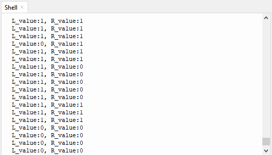
Values detected by the line tracking sensor are shown in the table.
The values of infrared tracking detection of objects with different colors in all cases. Where black object or no object is detected represents 1, and white object is detected represents 0.
Left |
Right |
Value(Binary ) |
0 |
0 |
00 |
0 |
1 |
01 |
1 |
0 |
10 |
1 |
1 |
11 |
3. Test Code
The line tracking sensors of the PCB board are controlled by GPIO7 and GPIO8 of the pico board.
Go to the folder KS3027 Keyestudio Beetlebot 3 in 1 Robot for Pico STEM Education\2. Python Tutorials\2.Python_Codes, You can save the code anywhere. For example, we save the code in the Disk(D)
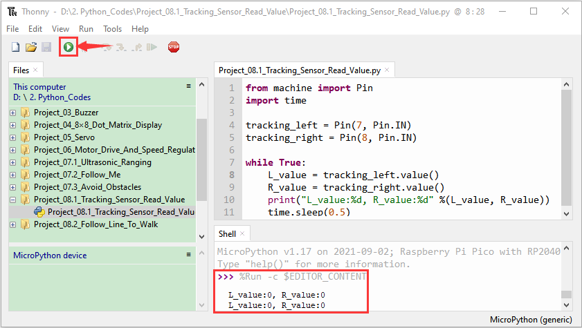
Open “Thonny”, click “This computer”→“D:”→“2.Python_Codes”→“Project_08.1_Tracking_Sensor_Read_Value.py” .

from machine import Pin import time tracking_left = Pin(7, Pin.IN) tracking_right = Pin(8, Pin.IN) while True: L_value = tracking_left.value() R_value = tracking_right.value() print("L_value:%d, R_value:%d" %(L_value, R_value)) time.sleep(0.5) |
4.Test Result:
Ensure the Raspberry Pi Pico is connected to the computer, and click“Stop/Restart backend”.

Click“Run current script. Put a black object under line tracking sensors and move it, you will see indicator light up and the Shell show values detected by the IR line tracking sensor.
Click Ctrl+C or click“Stop/Restart backend”to exit the program.
The sensitivity can be adjusted by rotating the potentiometer. When the indicator light is adjusted to the critical point of on and off state, the sensitivity is the highest.
Project 8.2: Line Tracking
1.Description:
We have introduced the knowledge of motor drivers, speed regulation, and infrared line tracking. In this experiment, the car will perform different actions according to the values transmitted by the infrared tracking.
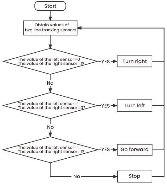
Working Principle:
Left |
Right |
Value(Binary ) |
State |
0 |
0 |
00 |
Stop |
0 |
1 |
01 |
Turn right |
1 |
0 |
10 |
Turn left |
1 |
1 |
11 |
Move forward |
Flow Chart:
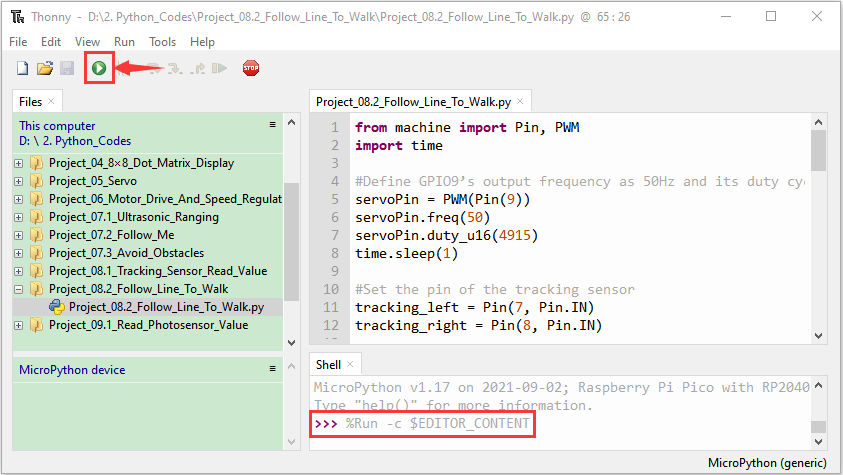
Test Result:
Ensure the Raspberry Pi Pico is connected to the computer, and click“Stop/Restart backend”.
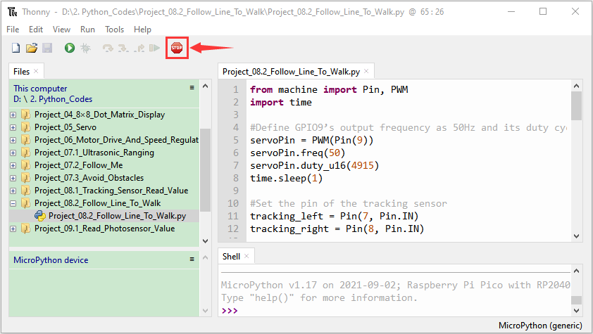
Place batteries in the battery holder, turn the power switch to the ON end, power up and put the car on a map we provide.
Click“Run current script”,then it will perform different functions via values sent by line tracking sensors. Press Ctrl+C or click
to exit the program.
Project 9: Light Following
We all know that humans can look for light in the dark with their eyes, but how do robots do this? For the robot to do this task, it first needs to be equipped with bright eyes, or light-sensitive sensors, so that the robot can find the light source by its strength. Our car is equipped with one photosensitive sensor on the left and the right.
When the light intensity and weakness of the external environment change, the resistance of the photosensitive sensor also changes accordingly, and this change is transmitted to the Nano board on the car, which judges and thinks like the human brain, directs the car to find light. Two photosensitive sensors constantly detect whether there is light, detect the light on the left and right sides of the judgment of which direction the light is stronger, and finally direct the car to the direction of strong light.
Project 9.1 Read Values
Description:
In this experiment, we will learn the working principle of the photoresistor.
2. Knowledge:
Photoresistor:
It mainly uses a photosensitive resistance element whose resistance varies from the light intensity. The signal terminal of the sensor is connected to the analog port of the microcontroller. When the light is stronger, the analog value at the analog port will increase; on the contrary, when the light intensity is weaker, the analog value of the microcontroller will reduce. In this way, the corresponding analog value can reflect the ambient light intensity.
3. Wire up:
Through the wiring-up diagram, signal pins of two photoresistors are connected to A6 and A7 of the Nano board.
For the following experiment, we use the photoresistor connected to A6 to finish experiments. First, let us read analog values.
Left photoresistor |
PCB board |
G |
G |
V |
V |
S |
S(GPIO26) |
4. Test Code
The left photoresistor is controlled by the GPIO26 of the pico board.
Go to the folder KS3027 Keyestudio Beetlebot 3 in 1 Robot for Pico STEM Education\2. Python Tutorials\2.Python_Codes, You can save the code anywhere. For example, we save the code in the Disk(D)
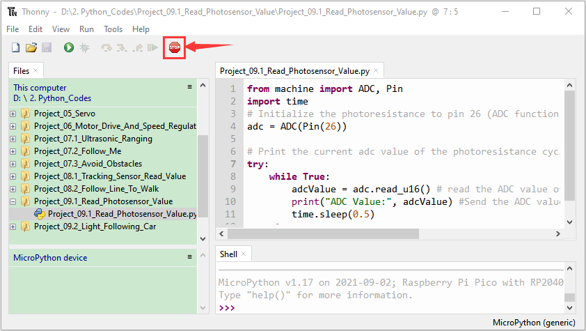
Open “Thonny”, click“This computer”→“D:”→“2.Python_Codes”→“Project_09.1_Read_Photosensor_Value”
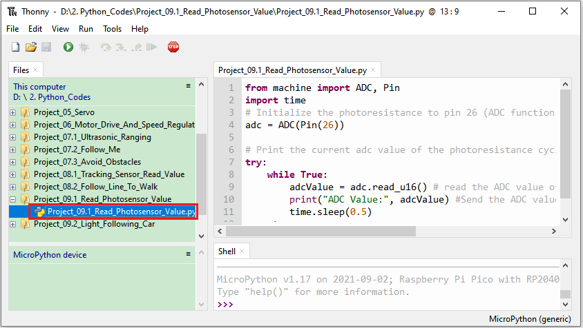
from machine import ADC, Pin import time # Initialize the photoresistance to pin 26 (ADC function) adc = ADC(Pin(26)) # Print the current adc value of the photoresistance cyclically try: while True: adcValue = adc.read_u16() # read the ADC value of photoresistance print("ADC Value:", adcValue) #Send the ADC value of photoresistance and print the result. time.sleep(0.5) except: pass |
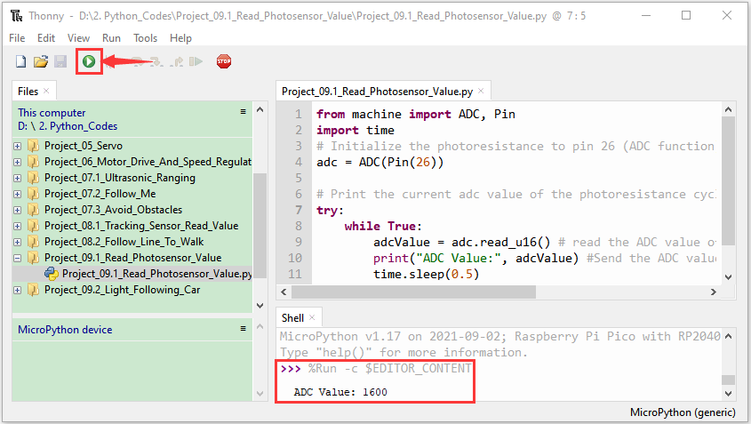
Ensure the Raspberry Pi Pico is connected to the computer and click“Stop/Restart backend”.
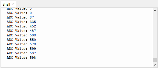
Click“Run current script”, we will see that when the light intensifies, the analog value will get increased; on the contrary, the analog value will get reduced. Press“Ctrl+C”or click“Stop/Restart Backend”to exit the program.
Project 9.2: Light Following Car
Description:
We have learned the working principle of photoresistor, motor and speed regulation. In this experiment, we will use a photoresistor to detect the intensity of light as as to achieve the light following effect.
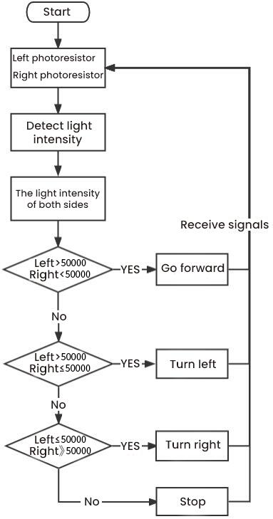
Working Principle:
Analog value of the left sensor |
Analog value of the right sensor |
Function |
>50000 |
>50000 |
Move forward |
>50000 |
≤50000 |
Move to left |
≤50000 |
>50000 |
Move to right |
<50000 |
<50000 |
Stop |
Wiring up:
| Left Photoresistor | PCB Board |
Right photoresistor | PCB Board |
|
| G | G | G | G | |
| V | V | V | V | |
| S | S(GPIO26) | S | S(GPIO27) |
Flow Chart:
Test Result:
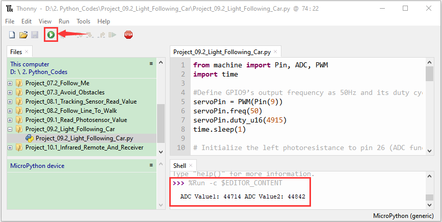
Ensure the Raspberry Pi Pico is connected to the computer, and click“Stop/Restart backend”.
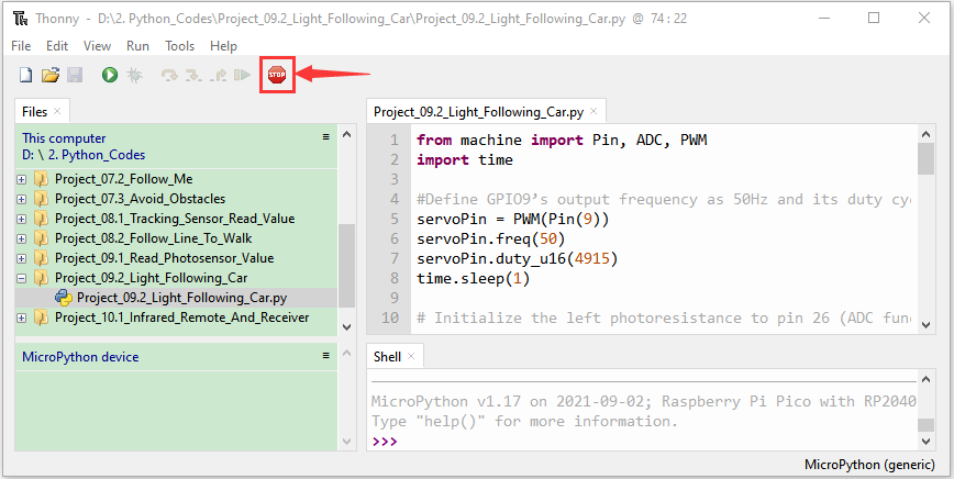
Place batteries in the battery holder, turn the power switch to ON end and click “Run Current Script”. We will see that the car will follow the light to move.
Press“Ctrl+C”or click“Stop/Restart Backend”to exit the program.
Project 10: IR Remote Control
Infrared remote controls are everywhere in daily life. It is used to control various home appliances, such as TV, speakers, video recorders and satellite signal receivers.
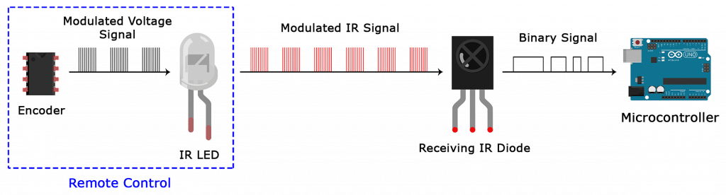
The remote control is composed of an IR emitter, an IR receiver and a decoding MCU. In this project, we will make a IR remote control car.
Project 10.1: IR Remote and Reception
1.Description:
In this experiment, we will combine the IR receiver and the IR remote control to read key values and show them on the serial monitor.
Knowledge:
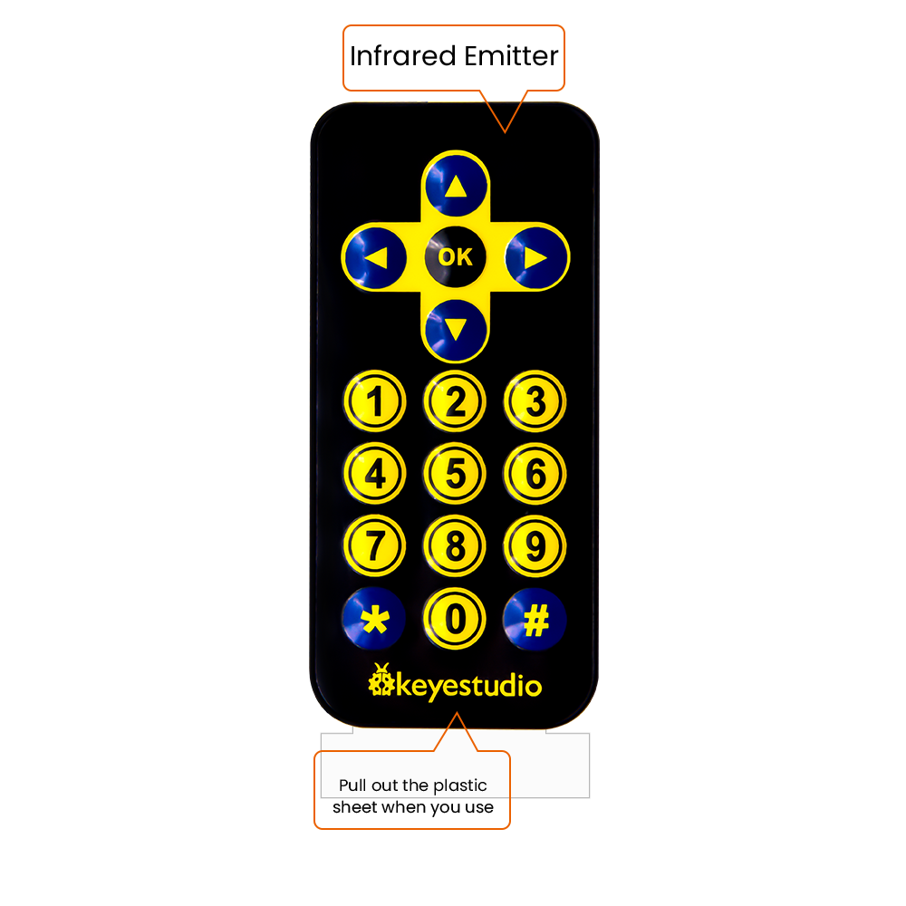
IR Remote Control:
It is a device with buttons. When the key is pressed, IR signals will be sent.
Infrared remote control technology is widely used, such as TVs, air conditioners and so on. And it can control air conditioners and TVs
The infrared remote control adopts NEC coding, and the signal period is 110ms.
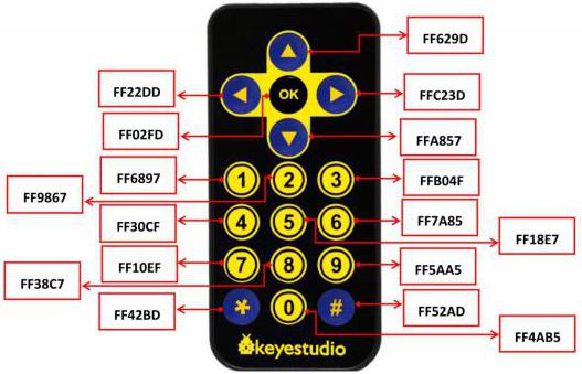
The remote control is shown below:
Infrared (IR) receiver:
It can receive infrared light and be used to detect the infrared signal emitted by the infrared remote control.
It can demodulate the received infrared light signal and convert it back to binary, and then transmit the information to the microcontroller.
NEC Infrared communication protocol:
NEC Protocol
To my knowledge the protocol I describe here was developed by NEC (Now Renesas). I’ve seen very similar protocol descriptions on the internet, and there the protocol is called Japanese Format.
I do admit that I don’t know exactly who developed it. What I do know is that it was used in my late VCR produced by Sanyo and was marketed under the name of Fisher. NEC manufactured the remote control IC.
This description was taken from my VCR’s service manual. Those were the days, when service manuals were filled with useful information!
Features
8 bit address and 8 bit command length.
Extended mode available, doubling the address size.
Address and command are transmitted twice for reliability.
Pulse distance modulation.
Carrier frequency of 38kHz.
Bit time of 1.125ms or 2.25ms.
Modulation
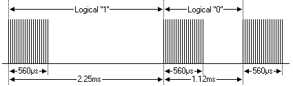
The NEC protocol uses pulse distance encoding of the bits. Each pulse is a 560µs long 38kHz carrier burst (about 21 cycles). A logical “1” takes 2.25ms to transmit, while a logical “0” is only half of that, being 1.125ms. The recommended carrier duty-cycle is 1/4 or 1/3.
Protocol
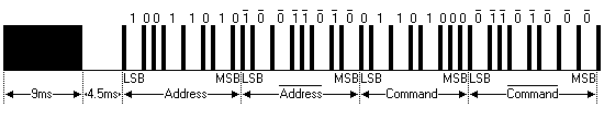
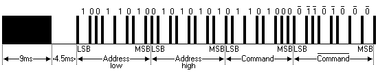
The picture above shows a typical pulse train of the NEC protocol. With this protocol the LSB is transmitted first. In this case Address $59 and Command $16 is transmitted. A message is started by a 9ms AGC burst, which was used to set the gain of the earlier IR receivers. This AGC burst is then followed by a 4.5ms space, which is then followed by the Address and Command.
Address and Command are transmitted twice. The second time all bits are inverted and can be used for verification of the received message. The total transmission time is constant because every bit is repeated with its inverted length. If you’re not interested in this reliability you can ignore the inverted values, or you can expand the Address and Command to 16 bits each!
Keep in mind that one extra 560µs burst has to follow at the end of the message in order to be able to determine the value of the last bit.
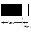
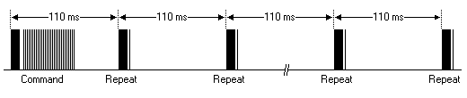
A command is transmitted only once, even when the key on the remote control remains pressed. Every 110ms a repeat code is transmitted for as long as the key remains down. This repeat code is simply a 9ms AGC pulse followed by a 2.25ms space and a 560µs burst.
Extended NEC protocol
The NEC protocol is so widely used that soon all possible addresses were used up. By sacrificing the address redundancy the address range was extended from 256 possible values to approximately 65000 different values. This way the address range was extended from 8 bits to 16 bits without changing any other property of the protocol.
By extending the address range this way the total message time is no longer constant. It now depends on the total number of 1’s and 0’s in the message. If you want to keep the total message time constant you’ll have to make sure the number 1’s in the address field is 8 (it automatically means that the number of 0’s is also 8). This will reduce the maximum number of different addresses to just about 13000.
The command redundancy is still preserved. Therefore each address can still handle 256 different commands.
Keep in mind that 256 address values of the extended protocol are invalid because they are in fact normal NEC protocol addresses. Whenever the low byte is the exact inverse of the high byte it is not a valid extended address.
Test Code
The IR receiver on the PCB board is controlled by GPIO6 of the pico board.
Go to the folder KS3027 Keyestudio Beetlebot 3 in 1 Robot for Pico STEM Education\2. Python Tutorials\2.Python_Codes, You can save the code anywhere. For example, we save the code in the Disk(D)
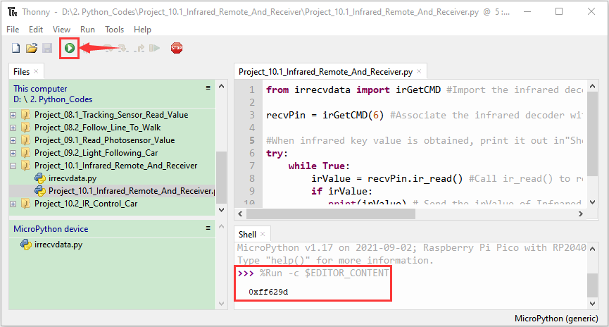
Open“Thonny”, click“This computer”→“D:”→“2.Python_Codes”→“Project_10.1_Infrared_Remote_And_Receiver”
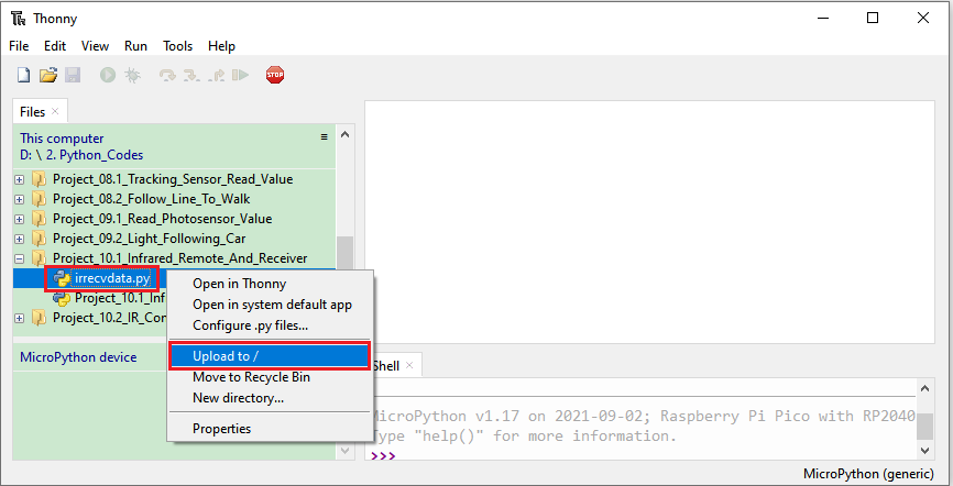
Select“irrecvdata.py”and right-click“Upload to /, after the“irrecvdata.py”is uploaded to the Raspberry Pi Pico,then double-click“Project_10.1_Infrared_Remote_And_Receiver.py”.
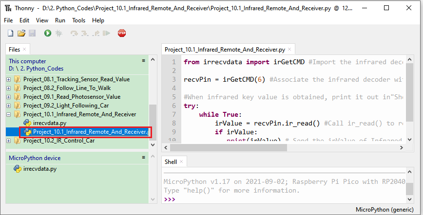
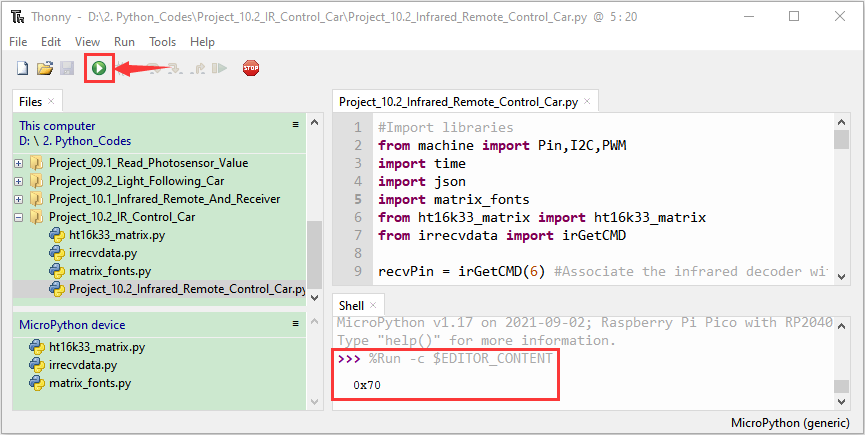
from irrecvdata import irGetCMD #Import the infrared decoder. recvPin = irGetCMD(6) #Associate the infrared decoder with Pin(6). #When infrared key value is obtained, print it out in"Shell" repetitively. try: while True: irValue = recvPin.ir_read() #Call ir_read() to read the value of the pressed key and assign it to IRValue. if irValue: print(irValue) # Send the irValue of Infrared Receiver and print the result. except: pass |
Ensure the Raspberry Pi Pico is connected to the computer,and click“Stop/Restart backend”.
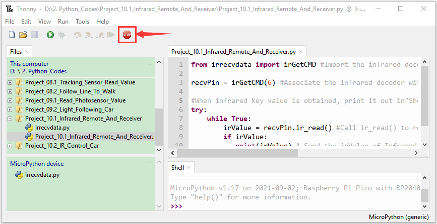
Click “Run Current Script” . Point at the infrared remote control at the infrared receiving head and press buttons on the controller, the “Shell” window under Thonny IDE will print the current received keycode value. Press “Ctrl+C” or click
“Stop/Restart
Backend” to exit the program.
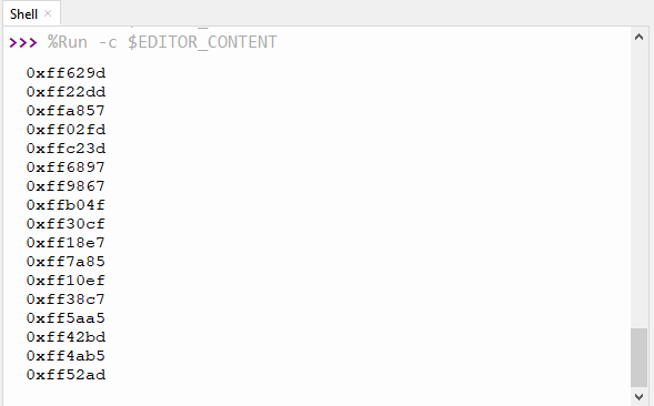
Write down the code associated with each button on the infrared remote, as we will need this information later.
Project 10.2: IR Remote Control Car
1.Description:
In the above experiment, we have learned about the knowledge of the 8*8 dot matrix display, the motor driver and speed regulation, the infrared receiver and the infrared remote control. In this experiment, we will use the infrared remote control and the infrared receiver to control the car.
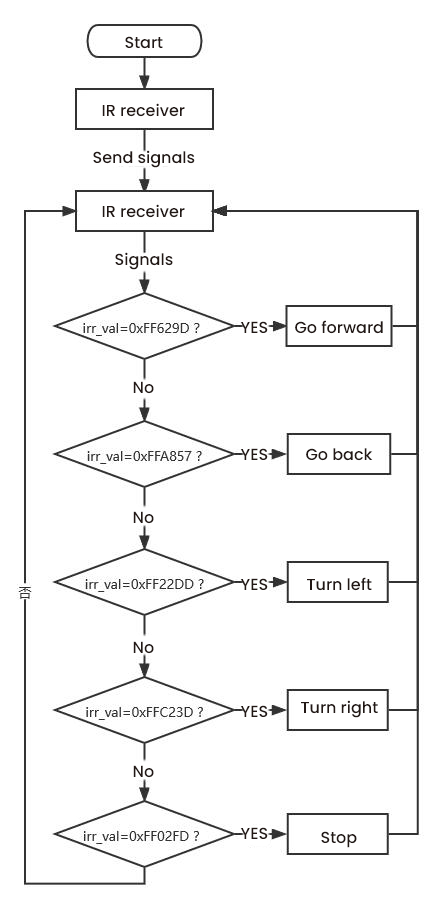
2.Working Principle:
Keys |
Keys Code |
Functions |
|
FF629D |
Go forward |
Display “forward”pattern |
||
|
FFA857 |
Go back |
Display “back”pattern |
||
|
FF22DD |
Turn left |
Show“left” pattern |
||
|
FFC23D |
Turn right |
Show“right turning”pattern |
||
|
FF02FD |
stop |
show“stop”pattern |


Flow Chart:
4. Test Code
Go to the folder KS3027 Keyestudio Beetlebot 3 in 1 Robot for Pico STEM Education\2. Python Tutorials\2.Python_Codes, You can save the code anywhere. For example, we save the code in the Disk(D)
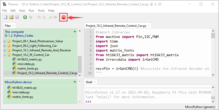
Open“Thonny”, click “This computer”→“D:”→“2.Python_Codes”→“Project_10.2_IR_Control_Car”
Select“ht16k33_matrix.py, irrecvdata.py and matrix_fonts.py and right-click Upload to /, then double-click Project_10.2_IR_Control_Car.py”
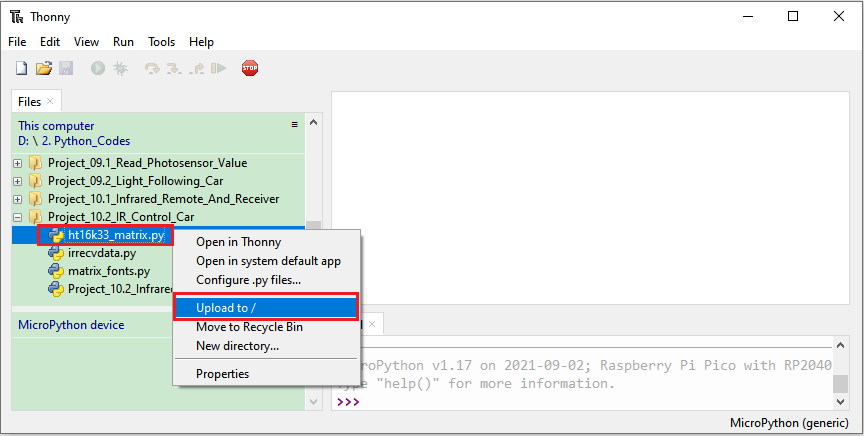
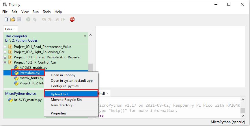
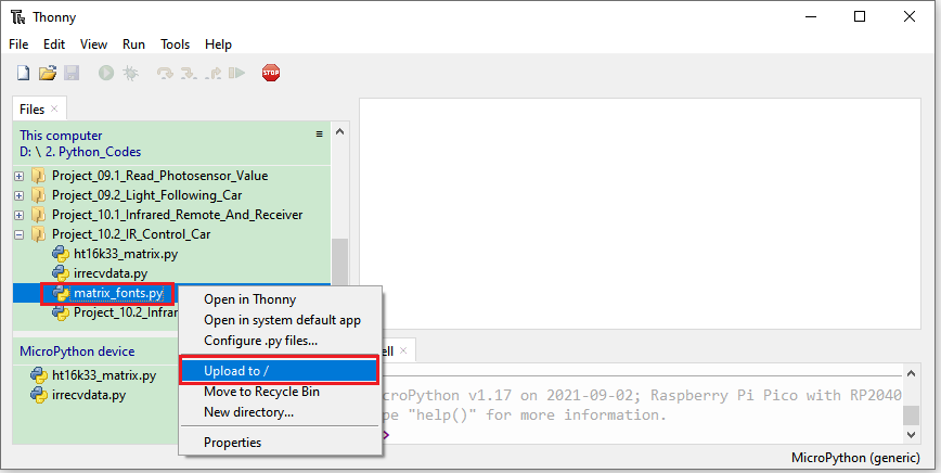
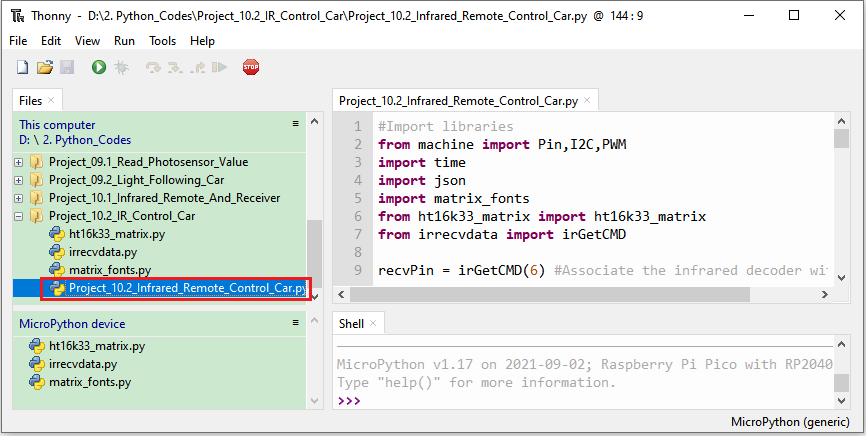
#Import libraries from machine import Pin,I2C,PWM import time import json import matrix_fonts from ht16k33_matrix import ht16k33_matrix from irrecvdata import irGetCMD recvPin = irGetCMD(6) #Associate the infrared decoder with Pin(6). ''' #Duty cycle corresponding to steering gear Angle 0°----2.5%----1638 45°----5%----3276 90°----7.5%----4915 135°----10%----6553 180°----12.5%----8192 ''' #Define GPIO9’s output frequency as 50Hz and its duty cycle as 4915, and assign them to PWM. servoPin = PWM(Pin(9)) servoPin.freq(50) servoPin.duty_u16(4915) time.sleep(1) # right wheel pin1=Pin(14,Pin.OUT) pin2=PWM(Pin(16)) pin2.freq(50) # left wheel pin3=Pin(15,Pin.OUT) pin4=PWM(Pin(17)) pin4.freq(50) ## Tool To Make Sprites https://gurgleapps.com/tools/matrix #i2c config clock_pin = 21 data_pin = 20 bus = 0 i2c_addr_left = 0x70 use_i2c = True def scan_for_devices(): i2c = machine.I2C(bus,sda=machine.Pin(data_pin),scl=machine.Pin(clock_pin)) devices = i2c.scan() if devices: for d in devices: print(hex(d)) else: print('no i2c devices') if use_i2c: scan_for_devices() left_eye = ht16k33_matrix(data_pin, clock_pin, bus, i2c_addr_left) def show_char(left): if use_i2c: left_eye.show_char(left) # As a function of the car going forward. def car_forward(): pin1.value(0) pin2.duty_u16(50000) pin3.value(0) pin4.duty_u16(50000) # As a function of the car going backwards. def car_back(): pin1.value(1) pin2.duty_u16(10000) pin3.value(1) pin4.duty_u16(10000) # As a function of the car going left. def car_left(): pin1.value(0) pin2.duty_u16(50000) pin3.value(1) pin4.duty_u16(32768) # As a function of the car going right. def car_right(): pin1.value(1) pin2.duty_u16(32768) pin3.value(0) pin4.duty_u16(50000) # As a function of the car stopping. def car_stop(): pin2.deinit() pin4.deinit() pin1.value(0) pin2.duty_u16(0) pin3.value(0) pin4.duty_u16(0) def handleControl(value): if value == '0xff629d': pin2=PWM(Pin(16)) pin2.freq(50) pin4=PWM(Pin(17)) pin4.freq(50) car_forward() #Car ahead # Dot matrix shows a forward pattern show_char(matrix_fonts.textFont1['^']) elif value == '0xffa857': pin2=PWM(Pin(16)) pin2.freq(50) pin4=PWM(Pin(17)) pin4.freq(50) car_back() # Car goes back # Dot matrix shows a backward pattern show_char(matrix_fonts.textFont1['v']) elif value == '0xff22dd': pin2=PWM(Pin(16)) pin2.freq(50) pin4=PWM(Pin(17)) pin4.freq(50) car_left() # Car to the left # Dot matrix shows a left pattern show_char(matrix_fonts.textFont1['>']) elif value == '0xffc23d': pin2=PWM(Pin(16)) pin2.freq(50) pin4=PWM(Pin(17)) pin4.freq(50) car_right() # Car to the right # Dot matrix displays a right pattern show_char(matrix_fonts.textFont1['<']) elif value == '0xff02fd': car_stop() # Car to the right # Dot matrix displays a stop pattern show_char(matrix_fonts.textFont1['!']) try: while True: irValue = recvPin.ir_read() #Call ir_read() to read the value of the pressed key and assign it to IRValue. if irValue: print(irValue) handleControl(irValue) except: pass |
4.Test Result:
Ensure the Raspberry Pi Pico is connected to the computer,and click“Stop/Restart backend”.
Place batteries in the battery holder, turn the power switch to ON end. Click “Run Current Script”, point the remote control at the infrared receiver, press keys on the remote control, then the car will show different functions. Press“Ctrl+C”or
click“Stop/Restart Backend”to exit the program.