Beetlebot Assemble
|
|||||||||||||||
Part 1 |
|||||||||||||||
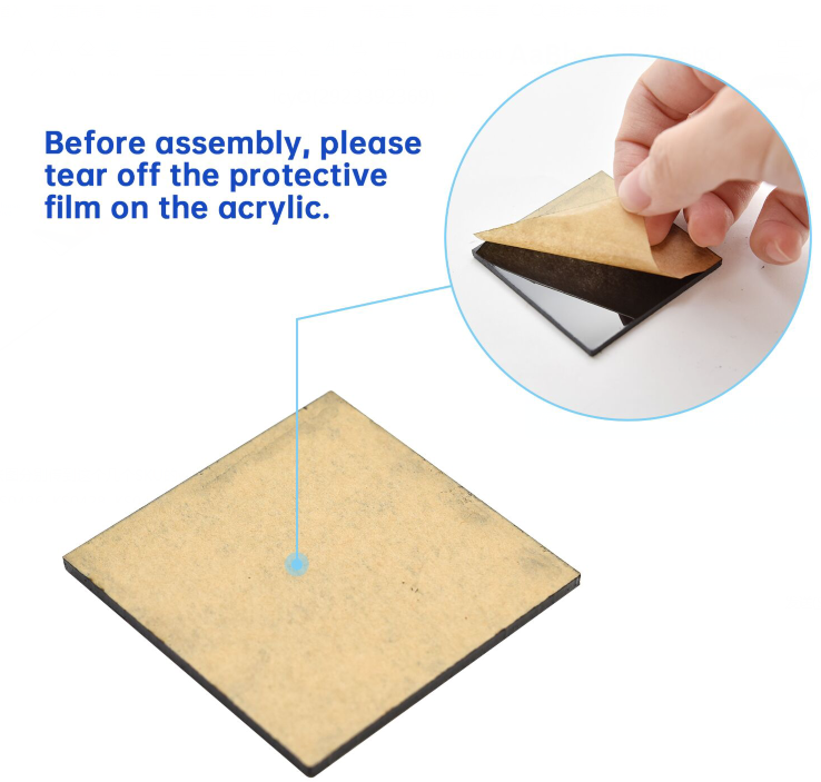
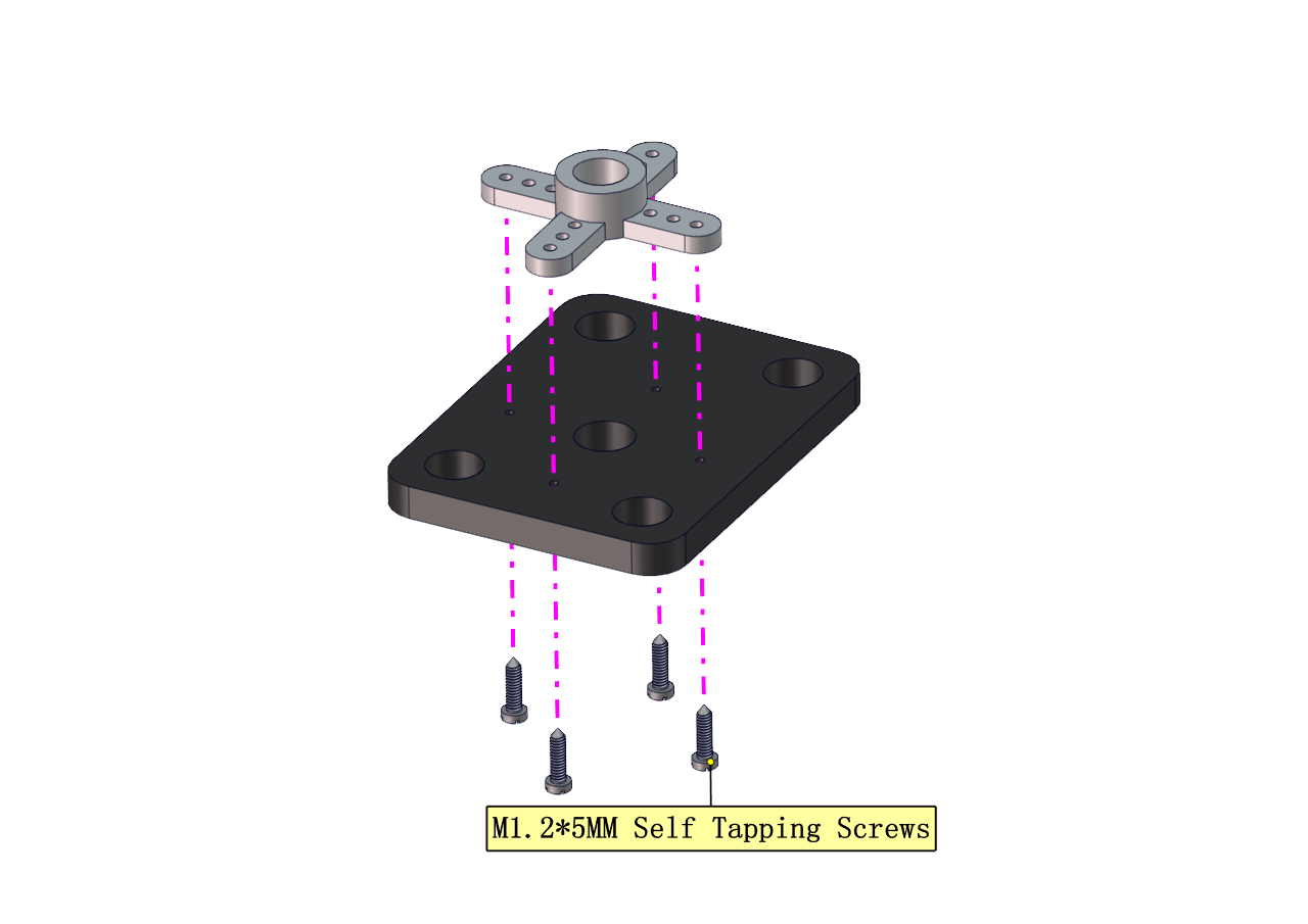
Components Needed |
|
||||||||||||||
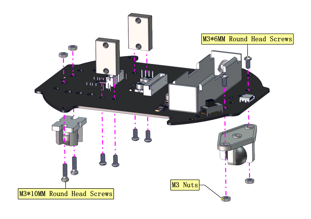
Installation Diagram |
|
||||||||||||||
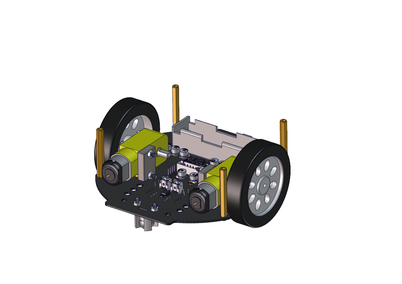
Prototype |
|
||||||||||||||
Part 2 |
|||||||||||||||
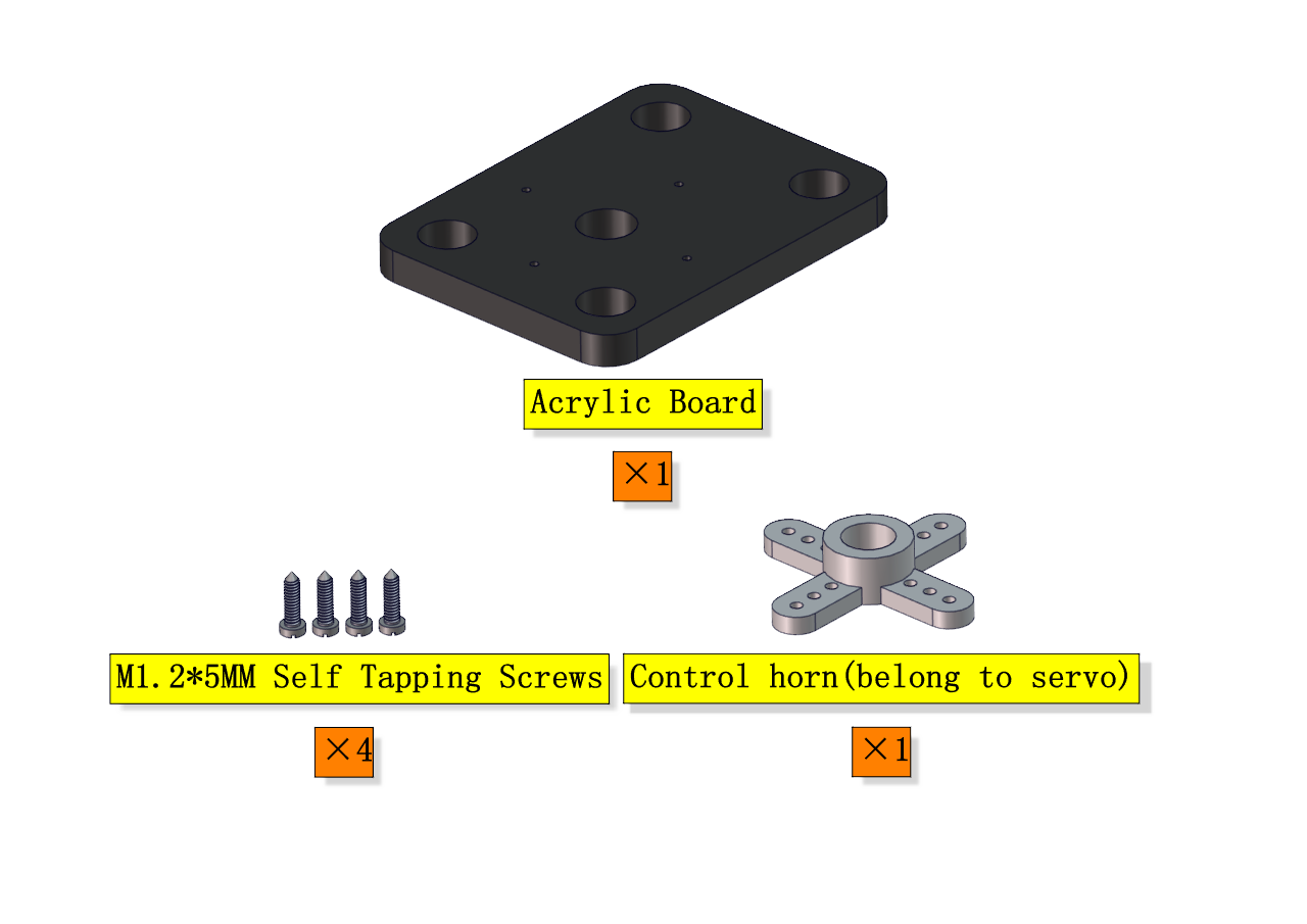
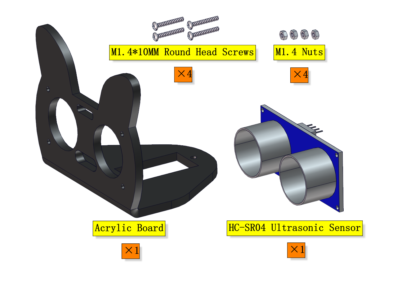
Components Needed |
|
||||||||||||||
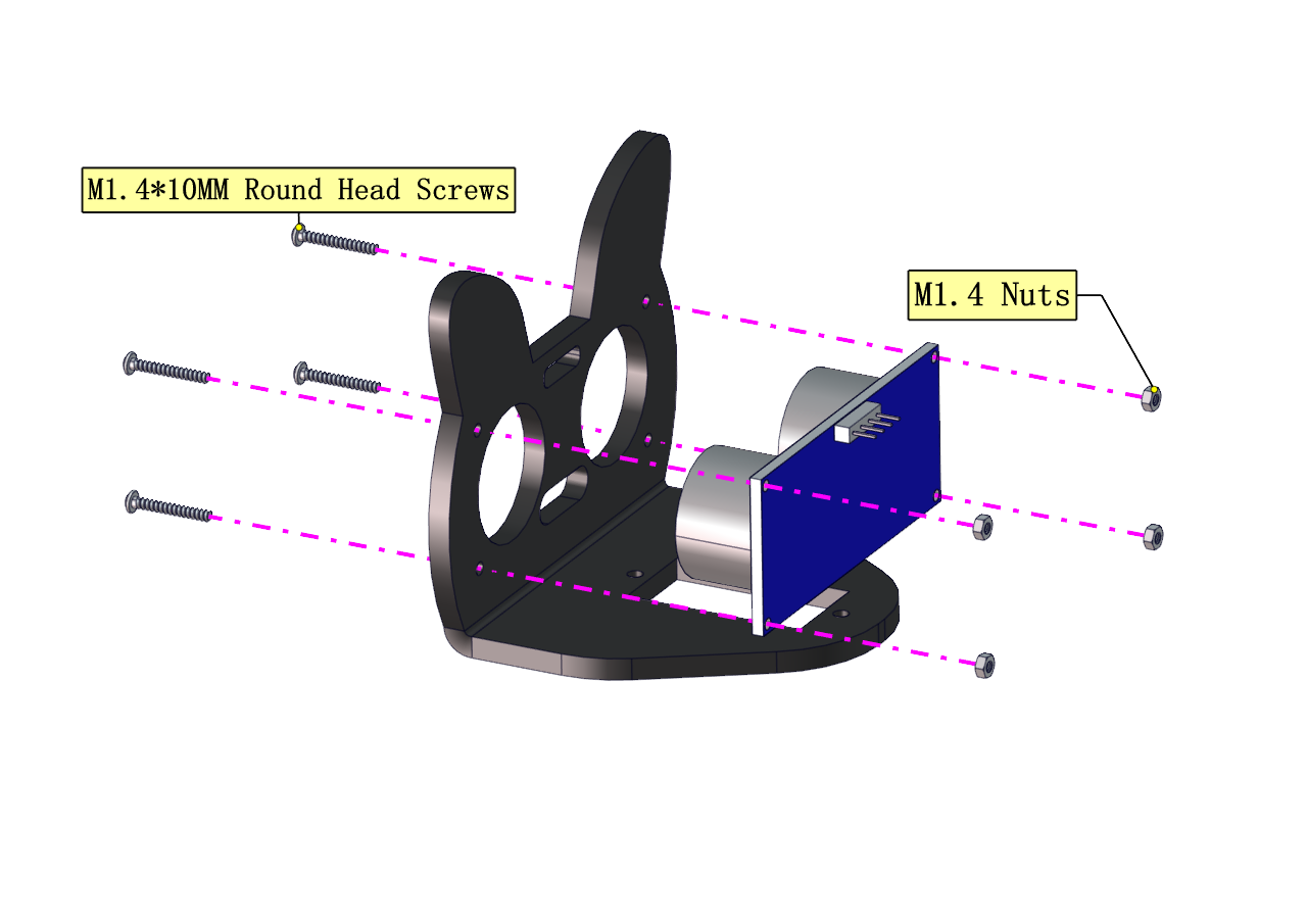
Installation Diagram |
|
||||||||||||||
Prototype |
|
||||||||||||||
Part 3 |
|||||||||||||||
Components Needed |
|
||||||||||||||
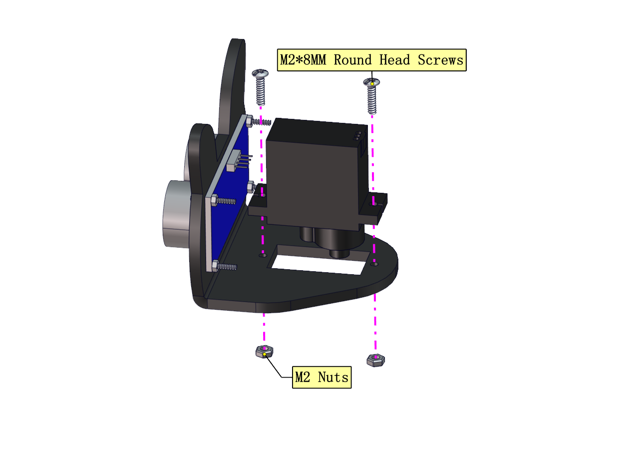
Installation Diagram |
|
||||||||||||||
Prototype |
|
||||||||||||||
Part 4 |
|||||||||||||||
Components Needed |
|
||||||||||||||
Installation Diagram |
|
||||||||||||||
Prototype |
|
||||||||||||||
Part 5 |
|||||||||||||||
Components Needed |
|
||||||||||||||
| Connect the wiring of the motor, 8*8 dot matrix and pcb boards |
|
||||||||||||||
Installation Diagram |
|
||||||||||||||
Prototype |
|
||||||||||||||
Part 6 |
|||||||||||||||
Components Needed |
|
||||||||||||||
Installation Diagram |
|
||||||||||||||
Prototype |
|
||||||||||||||
Part 7 |
|||||||||||||||
Components Needed |
|
||||||||||||||
Installation Diagram |
|
||||||||||||||
Prototype |
|
||||||||||||||
Part 8 |
|||||||||||||||
Components Needed |
|
||||||||||||||
Installation Diagram |
|
||||||||||||||
Prototype |
|
||||||||||||||
Part 9 |
|||||||||||||||
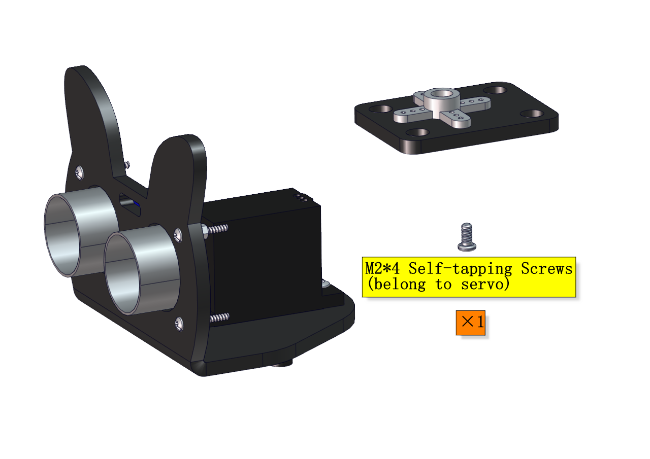
Components Needed |
|
||||||||||||||
| Set the servo to 90° before installation |
The above code is provided in the tutorial, open the initialization code of the servo and burn it to the Beetlebot's motherboard, as shown below:  |
||||||||||||||
| After adjustment, mount it forward |
|
||||||||||||||
Prototype |
|
||||||||||||||
Part 10 |
|||||||||||||||
Components Needed |
|
||||||||||||||
Installation Diagram |
|
||||||||||||||
Prototype |
|
||||||||||||||
Part 11 |
|||||||||||||||
Components Needed |
|
||||||||||||||
Installation Diagram |
|
||||||||||||||
Prototype |
|
||||||||||||||
Part 12 |
|||||||||||||||
Components Needed |
|
||||||||||||||
Installation Diagram |
|
||||||||||||||
Prototype |
|
||||||||||||||
| Complete installation |
|
||||||||||||||
Wiring Diagram |
|||||||||||||||
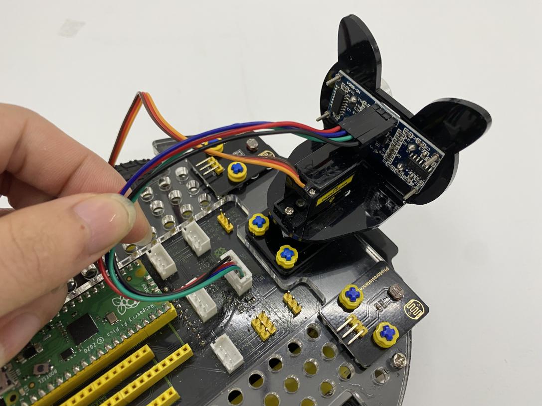
| Wiring Diagram of Ultrasonic sensor |
|
||||||||||||||
| Wiring Diagram of servo |
|
||||||||||||||
| Wiring Diagram of left Photoresistor |
|
||||||||||||||
| Wiring Diagram of right Photoresistor |
|
||||||||||||||
| Complete installation |
|
||||||||||||||